


Input Voltage at FIPL Sensor

Thread Starter
|
Junior User
Joined: Sep 2007
Posts: 94
Likes: 0
From: Versailles, KY
Input Voltage at FIPL Sensor
I've got a number of electrical issues, including a voltage leak somewhere. I've replaced the injection pump and remounted the FIPL (throttle position) sensor
and the E4OD transmission is acting up. When checking the voltages there, I found that the input voltage was around 5.7V. Also, the output voltage where it was supposed to be around 1.1V was about .45. Shouldnt' the input voltage at the FIPL sensor be 12V?
T
and the E4OD transmission is acting up. When checking the voltages there, I found that the input voltage was around 5.7V. Also, the output voltage where it was supposed to be around 1.1V was about .45. Shouldnt' the input voltage at the FIPL sensor be 12V?
T
Fleet Owner


Joined: Aug 2005
Posts: 23,667
Likes: 301
From: Easton,Ks
Fuel Injection Pump Lever sensor--E4OD
The screws holding the FIPL sensor bracket to the injection pump are epoxied, but enough adjustment may be achieved by loosening the screws holding the FIPL sensor to its bracket.
The FIPL should be adjusted using a scan tool. Remove the throttle cable and return spring, reinstall the spring so that the throttle is held to WOT. Enter and retrieve KOEO and Continuous trouble codes. After both fast and slow codes have been retrieved, turn on the scan tool speaker and press and release the OverDrive Cancel switch. Continue to press and release the ODC switch until the scan tool begins to beep repeatedly. A gauge block for the throttle lever can be improvised using the 13mm head of an 8mm bolt. Insert the head of the bolt between the flat boss on the right side of the injection pump and the throttle travel screw.
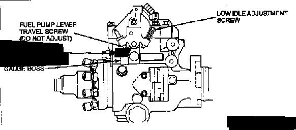
The beeping should become a steady tone. If it doesn't, loosen the FIPL sensor (T-15 torx screws) and adjust to get a steady tone; a faster beeping occurs when the the FIPL is set too low.
If a scan tool is not available, connect an ohm meter to the top and center FIPL terminals and adjust to 1800 ohms +/- 50 ohms. You can check the adjustment of the FIPL by back-probing the center wire of the FIPL sensor connector with a digital volt meter. The voltage should read 1.0-1.1 volts at idle, 1.6-1.9 at 30 MPH, and 2.0-2.5 at 55 MPH.
If these readings can't be achieved, replace the FIPL sensor and re-start this procedure. It may be necessary to remove the epoxy from the bracket screws (T-27 torx screws) to adjust a new FIPL sensor.
The screws holding the FIPL sensor bracket to the injection pump are epoxied, but enough adjustment may be achieved by loosening the screws holding the FIPL sensor to its bracket.
The FIPL should be adjusted using a scan tool. Remove the throttle cable and return spring, reinstall the spring so that the throttle is held to WOT. Enter and retrieve KOEO and Continuous trouble codes. After both fast and slow codes have been retrieved, turn on the scan tool speaker and press and release the OverDrive Cancel switch. Continue to press and release the ODC switch until the scan tool begins to beep repeatedly. A gauge block for the throttle lever can be improvised using the 13mm head of an 8mm bolt. Insert the head of the bolt between the flat boss on the right side of the injection pump and the throttle travel screw.
The beeping should become a steady tone. If it doesn't, loosen the FIPL sensor (T-15 torx screws) and adjust to get a steady tone; a faster beeping occurs when the the FIPL is set too low.
If a scan tool is not available, connect an ohm meter to the top and center FIPL terminals and adjust to 1800 ohms +/- 50 ohms. You can check the adjustment of the FIPL by back-probing the center wire of the FIPL sensor connector with a digital volt meter. The voltage should read 1.0-1.1 volts at idle, 1.6-1.9 at 30 MPH, and 2.0-2.5 at 55 MPH.
If these readings can't be achieved, replace the FIPL sensor and re-start this procedure. It may be necessary to remove the epoxy from the bracket screws (T-27 torx screws) to adjust a new FIPL sensor.
Last edited by subford; Dec 2, 2007 at 08:50 AM.
Thread Starter
|
Junior User
Joined: Sep 2007
Posts: 94
Likes: 0
From: Versailles, KY
Thanks guys,
I figured with all the other wiring problems I had that 5V supply to the FIPL sensor was just another one of them...
I probably need a new 'sensor'. According to lots of posts here and other Web sites these are notorious for going bad; and apparently Ford now has a more reliable design in gray. The transmission wasn't shifting well before I replaced the injection pump, so it probably wasn't only my inexperienced remounting of the sensor. I've got a code reader coming this week so I should be able to tweak the settings in the proper dieselman method if the existing sensor works. If not, I'll replace that and re-calibrate.
Thanks again,
T
Fleet Owner
Joined: Aug 2005
Posts: 23,667
Likes: 301
From: Easton,Ks
Originally Posted by tomherrick
I've got a number of electrical issues, including a voltage leak somewhere. I've replaced the injection pump and remounted the FIPL (throttle position) sensor
and the E4OD transmission is acting up. When checking the voltages there, I found that the input voltage was around 5.7V. Also, the output voltage where it was supposed to be around 1.1V was about .45. Shouldnt' the input voltage at the FIPL sensor be 12V?
T
and the E4OD transmission is acting up. When checking the voltages there, I found that the input voltage was around 5.7V. Also, the output voltage where it was supposed to be around 1.1V was about .45. Shouldnt' the input voltage at the FIPL sensor be 12V?
T
I would think 5.7V is to far off and would cause a lot of problems.

/
Thread Starter
|
Junior User
Joined: Sep 2007
Posts: 94
Likes: 0
From: Versailles, KY
I've gotta check #355 again to see if it's really 5.7V or just what it is.
The diagram you posted is much more readable than the one I've got in the Ford wiring diagram book. Is it available on-line?
Thanks,
T
The diagram you posted is much more readable than the one I've got in the Ford wiring diagram book. Is it available on-line?
Thanks,
T
Trending Topics
Fleet Owner
Joined: Aug 2005
Posts: 23,667
Likes: 301
From: Easton,Ks
Originally Posted by tomherrick
I've gotta check #355 again to see if it's really 5.7V or just what it is.
The diagram you posted is much more readable than the one I've got in the Ford wiring diagram book. Is it available on-line?
Thanks,
T
The diagram you posted is much more readable than the one I've got in the Ford wiring diagram book. Is it available on-line?
Thanks,
T
Ground return is circuit #359 and the position information circuit is #355 going back to the TECA.
The diagram is from the 1992 Ford E&VT Manual.
NOTE
If the #355 that you speak of is from your 1990 Wiring diagrams then you may have the right circuit as the numbers do change from year to year.
I am using the numbers of the above-posted 1992 diagram.
PS
MAP sensors use 5-Volts so it would have to be 5-Volts
Last edited by subford; Dec 2, 2007 at 10:17 AM.
FTE Stories
Ford Trucks for Ford Truck Enthusiasts

3 Best / 3 Worst Parts of Modern Ford Ownership
Brett Foote
10 Amazing Upgrades That Solve Common Ford Truck Owner Headaches
Pouria Savadkouei
Every 2026 Ford Engine Explained
Brett Foote
10 Ugly Ford Trucks That We Still Kinda Love
Joe Kucinski
10 Things Every Truck Owner NEEDS (2026 Edition)
Michael S. Palmer
Rezvani's Latest Post-Apocalyptic Monster Is a Ford F-150 Raptor Underneath
Verdad Gallardo
Top 10 Most Expensive Ford Trucks Ever Sold on Bring a Trailer
Joe Kucinski
2027 Ford Super Duty Buyer's Guide (Every Model, Engine, & Package)
Brett Foote
Top 10 Ford Truck Tragedies
Joe Kucinski
Thread
Thread Starter
Forum
Replies
Last Post
FORDF250HDXLT
Pre-Power Stroke Diesel (7.3L IDI & 6.9L)
117
Feb 10, 2025 11:29 PM
rterril02
Pre-Power Stroke Diesel (7.3L IDI & 6.9L)
25
Jun 4, 2020 08:44 PM
heythere2321
Pre-Power Stroke Diesel (7.3L IDI & 6.9L)
2
Oct 27, 2016 04:21 AM