


4 lo wont engage

Thread Starter
|
New User
Joined: Dec 2004
Posts: 4
Likes: 0
hey guys i got a 2000 ranger 3.0 4x4 i love the truck, ive got two questions 1. It wont engage into four wheel low range, any idea ive heard that alot of people have problems with this. I would buy the shift motor but thats almost 300 dollars so i dont want to unless thats definitly whats wrong. It engages everytime into 4 wheel high. If anyone knows or thinks whats wrong let me know. 2... whats the biggest tire i can fit onto it i was wondering if 32x11.50 will fit or just 31's this is at stock height or i might put blocks in the back and turn the torsion bars up. Let me know what you all think thanks.
Post Fiend
Joined: Jan 2003
Posts: 9,748
Likes: 16
From: Connecticut
Welcome to FTE!
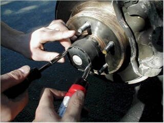
Because it's a 2000, your truck could have either the "Pulse Vacuum Hublock" (PVH) 4x4 system (used '98 - mid '00) or the "Constant Engagement" system (late '00 - present). For some reference, the PVH hubs are encased in hard black plastic and have a little screen on the end of them:
Which 4x4 system does your Ranger have?
In any case, it is common to both 4x4 systems that three conditions must be met in order to shift in and out of 4WD LOW:
1) The automatic transmission must be in neutral or the manual clutch depressed.
2) The brake must be applied.
3) The vehicle speed must be less than 5 km/h (3 mph).
Post Fiend
Joined: Jan 2003
Posts: 9,748
Likes: 16
From: Connecticut
If it shifts into 4WD HIGH but not 4WD low, then I'd say you're probably looking at a transfer case issue. pagosasam is on the right track by suggesting you check the brake light circuit, which includes the Brake Switch, one of the important signal feeds into the system.
For starters, try and track down a suitable scanner and pull any trouble codes that may be stored in the computer, maybe something will show up and point you in the right direction. The 4WD Control Module on your '01 is capable of setting 4x4-related trouble codes which the PCM will store in memory and can be read with an OBD-II scanner that is capable of reading Ford proprietary codes.
In the meantime, here is the relevant stuff from the Ford Manual that also might help you diagnose the problem:
Transfer Case - Electronic Shift Control System (some late '00 and '01+ Rangers)
Four-wheel drive mode is selected using a rotary switch located on the instrument panel. With the vehicle ignition on, the on-board controller verifies and matches the shift motor position to the switch.
To shift in and out of 4WD low, three conditions must be met:
- The automatic transmission must be in neutral or the manual clutch depressed.
- The brake must be applied.
- The vehicle speed must be less than 5 km/h (3 mph).
Electric Shift Motor
The motor assembly and connector, mounted externally on the transfer case cover, drives an electric shift cam which moves the lockup fork and the reduction fork assembly to the selected vehicle drive position. An integral position sensor provides information to the electronic module on the current motor position.
Digital Transmission Range (DTR) Sensor
The DTR sensor is located on the outside of the transmission at the manual lever. The DTR sensor completes the start circuit in PARK and NEUTRAL, the reversing lamp circuit in REVERSE and the neutral sense circuit (4x4 only) in NEUTRAL. The DTR sensor also sends a digital output signal to the powertrain control module (PCM) indicating the position of the manual lever (P, R, N, D, 2, 1).
Clutch Pedal Position Switch
The clutch pedal position switch is located on the clutch pedal bracket. On vehicles equipped with manual transmissions, the clutch pedal must be fully depressed with the vehicle stopped in order to make a range shift from 4H to 4L, or from 4L to 4H.
Brake Switch
The brake switch is located on the brake pedal. The brake must be depressed in order to make a range shift from 4WD high to 4WD low or back.
Rotary Control Switch
The rotary control switch is located on the instrument panel. The switch consists of a **** with a night time illuminated pointer. The switch is used to select 2WD, 4WD high or 4WD low. The dash indicator light will illuminate when the 4WD high or low position is engaged.
Control Module, Electronic
The electronic control module controls the operation of the transfer case in response to the inputs from the brake switch, the DTR sensor, the clutch interlock switch, and the motor assembly through the actuation of the rotary control switch.
Transfer Case Power Flow
The Borg-Warner 13-54 Electric Shift Transfer Case provides LOW RANGE driving. This system has no selectable neutral.
In the 4x2 mode, torque from the transmission is transferred to the input shaft assembly, which in turn drives the rear output shaft that drives the rear axle assembly.
The 2W-4W shift is accomplished through the shifting of the lockup collar that engages the drive sprocket on the rear output shaft. The drive sprocket turns the drive chain, which turns the driven sprocket on the front output shaft assembly. The front output shaft assembly then drives the front driveshaft.
The high-low shift is accomplished when the reduction fork assembly moves the reduction hub to engage the complete carrier assembly to the output shaft. Torque from the input shaft assembly is then transmitted through the sun gear, which then turns the complete carrier assembly. The complete carrier assembly, now engaged to the output shaft, provides the reduction.
The unit is lubricated by a gearotor oil pump assembly that pumps the oil through the bore in the rear output shaft.
Transfer Case - Electronic Shift - Principles of Operation
The system mode is selected by the operator through the mode select switch (MSS) on the instrument panel. Shifts into 4WD HIGH can be made at any speed. When shifting into 4WD HIGH with the vehicle stationary, tooth blockage may occur preventing shift completion. When the vehicle is driven above 8 km/h (5 mph) the shift will complete. When shifting in or out of 4WD LOW, the four-wheel drive (4WD) control module requires that the vehicle speed be less than 5 km/h (3 mph), the brake pedal be applied, and the transmission be in NEUTRAL (automatic transmission) or the clutch pedal be depressed (manual transmission).
The gearmotor encoder assembly is mounted externally on the transfer case. It drives a rotary cam which moves the mode fork and range fork within the transfer case between the 4WD HIGH, 4WD LOW, and 2WD range positions.
The four-wheel drive (4WD) Control Module controls the gearmotor encoder assembly that shifts between 4WD HIGH, 4WD LOW, and 2WD modes.
Feature inputs:
- brake ON/OFF switch
- mode select switch (MSS)
- digital transmission range (TR) sensor
- vehicle speed signal transmitted from the powertrain control module (PCM)
- TC contact plate position inputs A, B, C, D
Feature outputs:
- 4WD LOW indicator (ground when activated, open circuit when deactivated)
- 4WD indicator (ground when activated, open circuit when deactivated)
- 4WD shift motor outputs
Inspection and Verification � Electronic Shift
Visually inspect the following for obvious signs of mechanical and electrical damage.
Mechanical inspection:
Axle shafts and universal joints
Driveshaft and universal joints
Fluid leaks
Matching tire size
Electrical inspection:
-Battery junction box (BJB) fuses:
- Fuse # 1 (50A)
- Fuse # 3 (50A)
- Fuse # 13 (20A)
- Fuse # 30 (10A)
-Central junction box (CJB) fuses:
- Fuse # 28 (7.5A) (manual transmission)
- Fuse # 10 (7.5A)
- Fuse # 11 (7.5A)
- Fuse ## 5 (15A)
-4WD control module
-Wiring harness
-Mode select switch (MSS)
-Gearmotor encoder assembly
-Connector(s)
-Circuitry

Freshman User
Joined: Feb 2005
Posts: 34
Likes: 0
From: East Bay Area, CA
the only thing I'd add to that is that if it's a manual tranny, depress the clutch pedal AND put the shifter in the neutral position. I don't know for sure if there's a sensor for that, but I seem to remember being told to do that.
Trending Topics

Senior User
Joined: Oct 2004
Posts: 123
Likes: 0
From: Central Jersey
My 97 will only go into 4WDL when the truck is stopped, clutch depressed and stick in neutral.
FTE Stories
Ford Trucks for Ford Truck Enthusiasts

10 Things Every Truck Owner NEEDS (2026 Edition)
Michael S. Palmer
Rezvani's Latest Post-Apocalyptic Monster Is a Ford F-150 Raptor Underneath
Verdad Gallardo
Top 10 Most Expensive Ford Trucks Ever Sold on Bring a Trailer
Joe Kucinski
2027 Ford Super Duty Buyer's Guide (Every Model, Engine, & Package)
Brett Foote
Top 10 Ford Truck Tragedies
Joe Kucinski
AEV FXL Super Duty - the Super Duty Raptor Ford Doesn't Make
Brett Foote
Lobo Vs Lobo: Proof the F-150 Lobo Should Be Even Lower!
Michael S. Palmer
Ford's 2001 Explorer Sportsman Concept Looks For a New Home
Verdad Gallardo
10 Best Ford Truck Engines We Miss the Most!
Joe Kucinski
Thread
Thread Starter
Forum
Replies
Last Post
hodge66
1983 - 2012 Ranger & B-Series
2
Nov 22, 2014 09:51 AM