When you click on links to various merchants on this site and make a purchase, this can result in this site earning a commission. Affiliate programs and affiliations include, but are not limited to, the eBay Partner Network.
This is going to sound odd, but you need to give it time for the springs to settle / learn their position.
when I was doing my TCI install I was concerned about this too (had a very similar looks as yours) and called them and they told me the same thing and my options were either leave it that way until I add all the parts on the truck in which case the springs will settle and in time learn their position after several hundred miles of driving, or I could take a 7/8" threaded rod (18" long) through the UC, spring & LC with 1/4" steel plates (with 7/8" hold drilled in them) on top of the spring perch and the bottom of the LC with nuts on both ends of the rod (lower part of rod about 1" of thread) and crank the nut on the top to compress the springs down (I needed vise grip to hold the rod from spinning) to where the lower control arms are almost parallel to the ground to simulate the full weight on the front.
They told me to leave it that way for a month or so, I think I waited 2 months. Then you remove the rods, and install your shocks. The rods allow the springs to learn the "at rest" position of the fully loaded truck. When I put the shock in I had to put a jack under the LC to compress the spring about an inch to be able to get the upper shock bushing, washer & nut on the shock rod, but prior to doing the 7/8" rod trick there was no way I could install the shock even with a jack under the LC. The springs were so stiff I was lifting the truck. The rod trick definitely works.
Jim
This sounds like a great idea. I already have the threaded rod. And easily have the time to let it sit compressed. Once I have it setup I’ll post some pics. Thanks Jim 😊
This sounds like a great idea. I already have the threaded rod. And easily have the time to let it sit compressed. Once I have it setup I’ll post some pics. Thanks Jim 😊
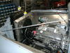
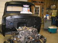
It worked out pretty good for me. I'm doing paint work right now on mine but here are some pics of how my chassis sits today after doing the threaded rod trick. As you can kind of see through the plastic I just have the engine/tranny, and radiator with front deflectors / inner fenders installed, so there is not much weight on the front end and the lower control arm sits pretty good already.
It will relax even more as I start adding the cab, hood, fenders, etc..
It worked out pretty good for me. I'm doing paint work right now on mine but here are some pics of how my chassis sits today after doing the threaded rod trick. As you can kind of see through the plastic I just have the engine/tranny, and radiator with front deflectors / inner fenders installed, so there is not much weight on the front end and the lower control arm sits pretty good already.
It will relax even more as I start adding the cab, hood, fenders, etc..
Jim
That is a good look from the bottom. Thanks again for this suggestion.
It worked out pretty good for me. I'm doing paint work right now on mine but here are some pics of how my chassis sits today after doing the threaded rod trick. As you can kind of see through the plastic I just have the engine/tranny, and radiator with front deflectors / inner fenders installed, so there is not much weight on the front end and the lower control arm sits pretty good already.
It will relax even more as I start adding the cab, hood, fenders, etc..
Jim
Jim
This picture is very helpful. Look at the steering shaft locations from yours to Olignays, there are noticeable differences. With the c-notch in the frame it leads me to believe Olignays cross member is higher in the frame.
I'm not sure I understand what you're referring to . The lower rack mount bolt is reasonable close to even with the lower control arm bolt on both ( they are different year-model trucks ) . The only thing I would guess at it is possible that the crossmember is deliberately designed for a drop but in any case if the top hats and upper control arms are mounted properly it would still be the springs . I am certainly no suspension expert but shouldn't the upper and lower inner control arm mounts should be the same distance apart as the outer mounting points on the spindle ?
I have the Jims rod shop front end in mine and went with 700 lbs springs because I ran out of room with adjustable shocks they had sent 600 lbs springs with kit. I have a ford 400 in it. Will try to get some pictures posted.
So I installed the threaded rod on the RH side and compressed the spring about two inches and this is how the lower arm is now located. I can definitely tighten the rod more to get it closer to parallel. I also took a couple of rough measurements. It is ~10.25” between the UCA and LCA pivot points. It’s. Also ~10.25’” from inside the spring hat to the centre of the lower shock mounting bolt. Not sure if these numbers make any sense.
I also measured the wire diameter of my springs and they are 0.600”. When I compare them to speedway springs I’m guessing mine have a spring rate between 300-350 lbs as speedway is 0.580” and 0.610” respectively.