Temp and fuel gauge
#1
Temp and fuel gauge
All wiring done inside the cab. But my temp gauge and fuel gauge are not working.the ggauges are stock 53 f100. I am connecting a Chevy sender switch to the gauge. Could this be the problem? Which post should the power wire be connected to? Same for the fuel gauge, how do you know which post to connect power wire and which post to connect the wire from the sender?
#2
Stock, 6V gauges must be used with the matching stock, 6V sending units. The Chevy senders won't work. Ford and Chevy gauges, especially the type Ford used back then work on a different electrical principle and are not compatible with each other. If you're running 12 volts, you'll need to add a voltage reducer to keep from burning them out.
#3
Stock, 6V gauges must be used with the matching stock, 6V sending units. The Chevy senders won't work. Ford and Chevy gauges, especially the type Ford used back then work on a different electrical principle and are not compatible with each other. If you're running 12 volts, you'll need to add a voltage reducer to keep from burning them out.
#4
#5
The original gauges are not polar sensitive. They work wired either way.
As Wayne pointed out, they will not react properly to a modern resistance based sending unit. As I understand it, the original sends a "pulse" type signal.
If you want to use the bowtie sending unit, you will need a replacement gauge.
1953-55 Ford F-100 Temperature Gauge And Sender Kit, With 1/8 Npt Sender, Mf (midfifty.com)
#7
The stock sending unit uses the The King-Seeley (Ford Stock) principle. These sending units supply a full 6V through the heater wire in the gauge in the form of a square wave with the duration of the "on" being the variable determining the gauge reading. The longer the duration, the more fuel in the tank. It is this full 6v of current which heats the bi-metallic strip in the stock gauge that causes the gauge to read via a small gear train (that may adjustable). Most other makes and after market sending units are simply a variable resistor which sends a constant voltage to the gauge, lessening that voltage as the fuel level goes down. Therefore, the sending units signal doesn't heat the bimetallic strip in the gauge as much. Unfortunately, the calibration of the after-market sending units and the stock gauges don't match up very well due to the differences in the principle of the signal. Additionally, voltage reducers do not magically make incompatible senders and gauges talk to each other correctly either.
Bottom line, if you want stock gauges, you need stock style sending units. If you are running 12V, you also need to incorporate a voltage reducer.
Bottom line, if you want stock gauges, you need stock style sending units. If you are running 12V, you also need to incorporate a voltage reducer.
Trending Topics
#8
#10
#11
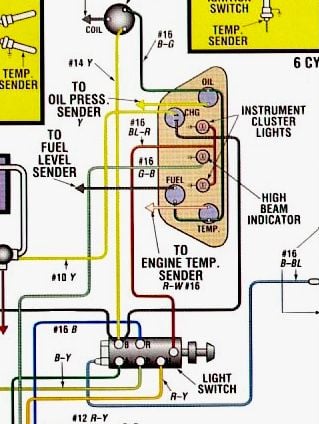
On the gauge, one terminal goes to the sending unit. The other terminal goes to power ( not ground). In the diagram above, it is taken from the ignition switch switched power. The voltage reducer is likely to be installed between the ignition switch and the bus for the gauges, but confer with the voltage regulator documentation.
#12
The stock sending unit uses the The King-Seeley (Ford Stock) principle. These sending units supply a full 6V through the heater wire in the gauge in the form of a square wave with the duration of the "on" being the variable determining the gauge reading. The longer the duration, the more fuel in the tank. It is this full 6v of current which heats the bi-metallic strip in the stock gauge that causes the gauge to read via a small gear train (that may adjustable). Most other makes and after market sending units are simply a variable resistor which sends a constant voltage to the gauge, lessening that voltage as the fuel level goes down. Therefore, the sending units signal doesn't heat the bimetallic strip in the gauge as much. Unfortunately, the calibration of the after-market sending units and the stock gauges don't match up very well due to the differences in the principle of the signal. Additionally, voltage reducers do not magically make incompatible senders and gauges talk to each other correctly either.
Bottom line, if you want stock gauges, you need stock style sending units. If you are running 12V, you also need to incorporate a voltage reducer.
Bottom line, if you want stock gauges, you need stock style sending units. If you are running 12V, you also need to incorporate a voltage reducer.
#13
#14
@shadderszxr , the proper way to test your stock gauges is in the service manual (pg 275 I think) with D Cell Batteries. A single D Cell should read half way, 2 D Cells should max the gauge out.
The following users liked this post:
#15
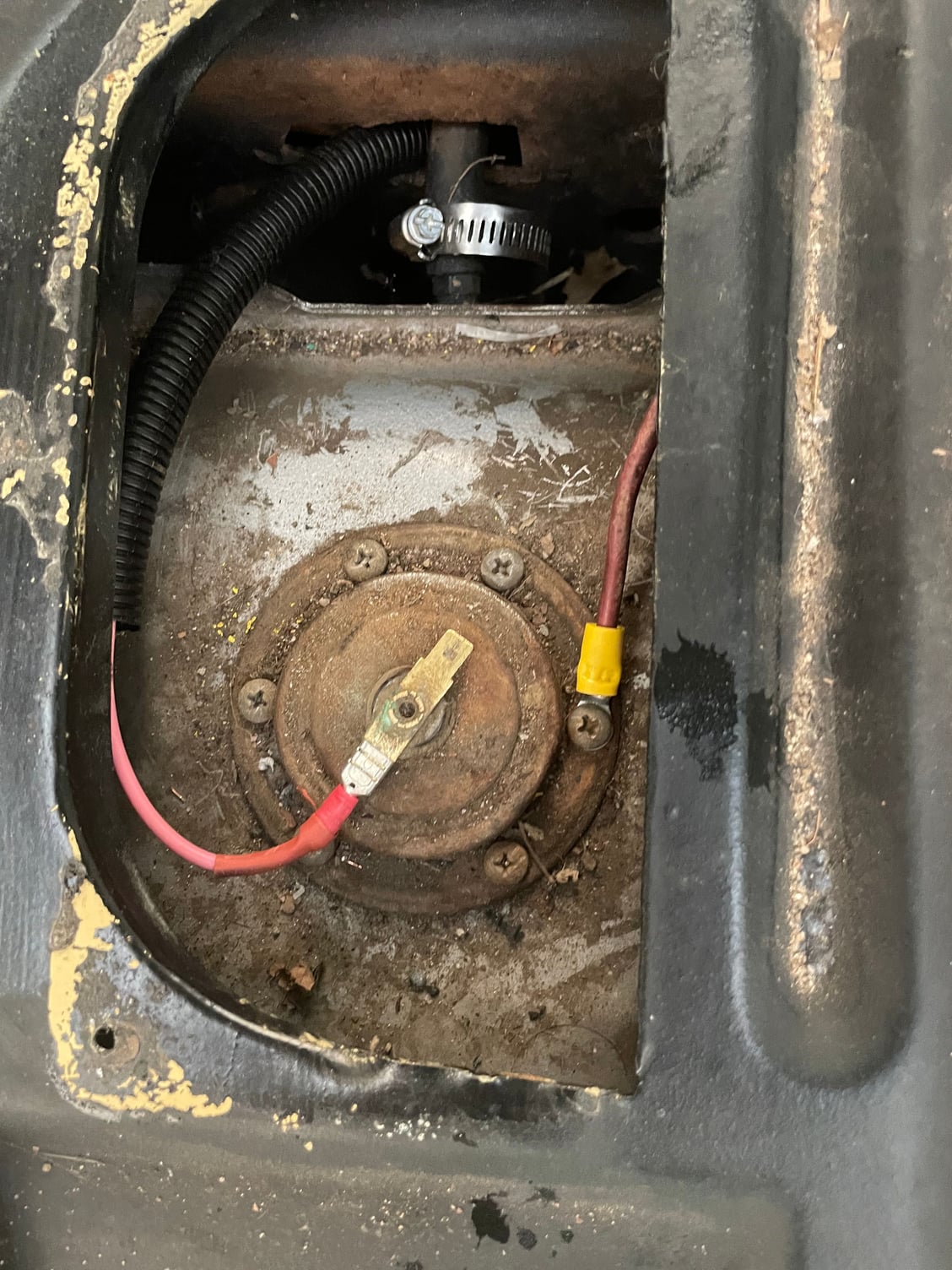
@Pappys53 , looks like you could use some cleaning to make some good electrical contact, both on the ground and the signal wire. CRC 2-26 or similar contact cleaner as well as some scotchbrite to ensure good grounding through the bolt contact area and the spade terminal for the signal wire.
It seems you have wires in the correct locations, with the ground going to the screw on the outside and the signal wire going to the center terminal.
It seems you have wires in the correct locations, with the ground going to the screw on the outside and the signal wire going to the center terminal.


