When you click on links to various merchants on this site and make a purchase, this can result in this site earning a commission. Affiliate programs and affiliations include, but are not limited to, the eBay Partner Network.
Ok, so here's the requested install I did on the Pro Comp brand traction bars
My truck is a late '99, 4x4, CCLB, with ZF6 transmission
The Pro Comp kit for our trucks is # 72400B (bars only) 72099B (mounting kit)
This is their stock photo, these are not the mounts for our trucks, but the kit comes with all the grade 8 bolts nuts & washers needed for install as i will show later. The bars are 66" long & weigh in at 22.5# each without the bushings installed like in the photo above
The included instructions need some fine tuning. It's 2 pieces of paper stapled together, printed front and back, and the page numbers aren't in logical order, I'd recommend downloading the install instructions i included below in PDF beforehand for ease of navigation and some pre-assembly throne reading
The first step was to spray a coat of clear paint on the bars and mounts after removing one tiny ball of MIG welding spatter from inside 1 bar where the poly bushing would go. They come powdercoated, but... I'm kinda picky. To begin install, park on a flat surface. Next, spray your favorite type of nut freeing lube on the u-bolt nuts, then chock the front wheels. I put it in 4wheel before hand to keep the front tires locked. Jack up the truck tire partway so you can remove the rear wheel on the side you are working on, before the tire leaves the ground break the lug nuts loose, once they are free contine jacking the wheel up off the ground a couple inches. Next slide some jack stands under the frame, to get the stands under the frame i went in front of the springs and at the rear of the frame by the bumper with the second one. Then remove the wheel. Next up, very important! Remove the lower shock bolt. You don't want your axle hanging by the shock! Also unbolt your factory sway bar. I had to unbolt my Helwig sway bar.
The first hands on step was to remove the riser block from between the axle and spring pack. Ideally use a 2' breaker bar for the first turn or two of the nuts before switching to a ratchet. Or an impact if you feel lucky. We used a ratchet so we could feel any catches of the threads and know if there would be trouble. We did end up with some slight thread issues, but it wasn't bad enough to replace the ubolts, we just used a thread file to clean them up, if you have a metric die this size I'd recommend using it before reinstall. Once unbolted, lower the jack, make sure your jack stands don't lean. Once the springs and axle seperated the alignment pin popped out of place. Don't mess your pants when it happens, but make sure that is actually the noise you heard. This will make the springs no longer aligned with the axle. We had to use a chain hoist/come along and prybars to realign them
Next step, eh, more complicated. The vague instructions say to extend the alignment pin on the bottom of the block to accommodate the extra thickness we will be adding of the 1/4" thick mounts, by drilling a hole for the included allen bolt thru the alignment pin. So we chucked it up in the milling machine and centered it up
So, dad and i have too much experience in our line of work with people just sticking bolts thru holes where they should have used a pin and the vibrations from equipment will make the threads chew thru the hole, ruining parts. So we decided to tap the block pilot pin for the allen bolt instead of just simply and quickly drilling a hole thru it and having the bolt loosely run thru it. Plus being able to add red locktite to the bolt thru the block and nut ensured a more permanent alignment of the springs and mount
Here the included allen bolt is threaded into the stock alignment pin. So, depending on whether you want to go simple with just a hole, vs threaded like this will depend on which size hole you drill in the block pin. If you don't have the fancy setup we used above just mount the allen bolt in a drill press chuck to align it with the pin by feel, we tried it that way for proof of concept and it came out ok. The pin in the bottom of the block is not perfectly round and is tapered, so close your eyes and feel it up till you get it where you like it. Then drill
So this is how it would also look if we simply drilled a hole thru it, but it's threaded in. Long term the extra 30 minutes spent was worth it to us
Here's a picture of the mounts that go between the block and the axle, although when assembled it is oriented upside down from this picture as you will see below
Mount installed, block back in place, we still have to reattach the shocks and Helwig sway bar and torque the ubolts to 115 foot pounds.
As mentioned above we had to use a chain hoist to get the springs lined back up with the axle and all the mounting pins realigned. And after installing the other side as well that's where it went from "simple" to involved, cause next up you loosely mount the bars to the axle mounts and install the front mounts to the bar, then lift the front mounts up to frame to drill holes. But, since you just had to realign everything, there is a chance all that changed your axle's position, and since the next step solidly attaches it to the frame i drove the truck straight forward a couple hundred feet, then backed it back into the shop, all without touching the steering wheel. Just in case the axle's alignment was off a touch this would get it all back straight. In theory
Let's run thru the hardware
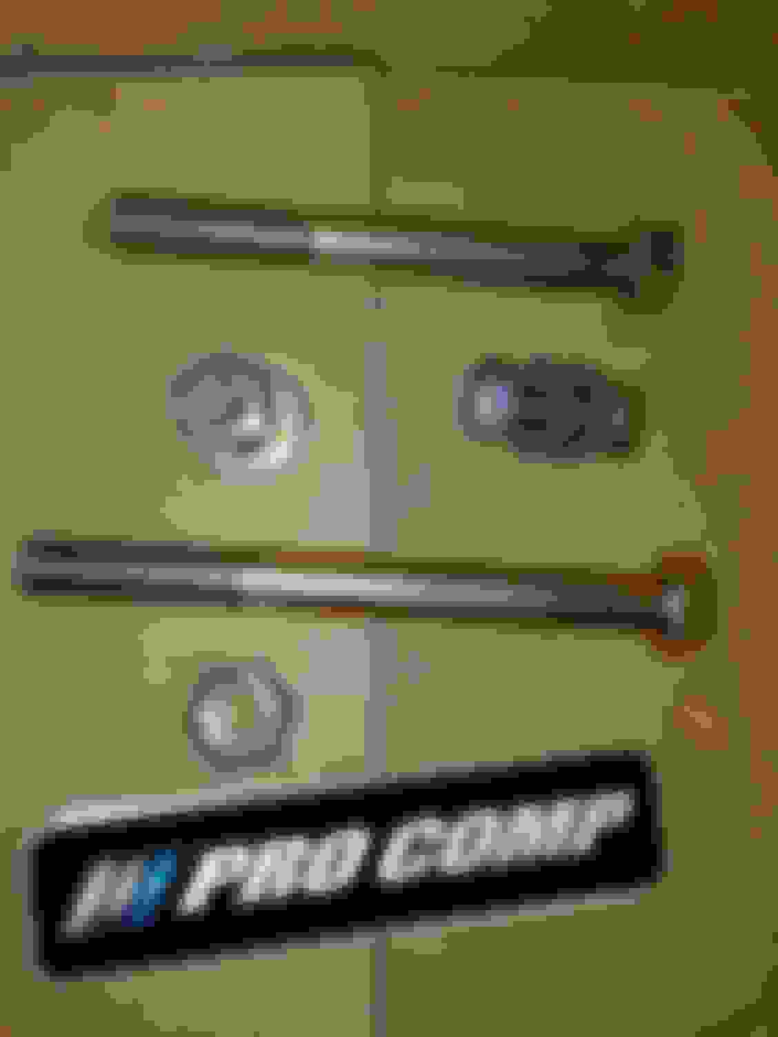
So, here is the included hardware, all the bolts are grade 8, no worry there
The lock nuts & bolts, with 2 washers per bolt
The front bar to frame mount, all the mounts are 1/4" thick and powder coated
The included locking nuts, but we still used red loctite everywhere
The poly bushings and sleeves
The sleeves are 1/8" thick
Assembled bushings with the sleeve inserted
So, for those of us with long beds, installing the DS bar, SUCKS. The larger/longer fuel tank will be in the way of the large horizontal mounting bolt for the front bar mount. We're going to sleep on our solution and potential fix for the next guy, but @ 30* in the shop and 4 hours into it we needed to do some milling on a locking nut and shortened the bolt to not rub the fuel tank. My hands were so filthy i didn't dare take photos during the process, and was really too busy trying to beat the clock for dinner on Valentine's. The short version is, fuel and brake lines are right behind the mounting holes when you drill the frame, as is the tank. The passenger side is comparatively a breeze. Long bed owners, expect trouble. Short bed, possibly less due to no tank interference?
So next you mount the bar to the rear mount. The bars are directional
As you can see here at the rear of the bar, the bar being straight in the photo the rear mounting tube is angled. That's because at the spring mount the bar is outside the frame rails, vs at the front mount of the bar you are directly under the frame. The easy way to tell which bar goes on which side is you want to read their brand from the out side of the truck, wrong way the words will be backwards and i doubt it would even bolt up
Like so
So, you push the poly bushings into the bar, then the sleeve thru the bushings, then lift the bar into place and slide the longer 9/16" bolt from the above pictures in with washers on each side and tighten the nut. Next, install the bushings in the front of the bar, then the sleeve, then bolt the mount to the bar. During the next step the bar actually becomes very heavy as you hold it firmly in place to the frame, and your helper begins to drill thru the mount's holes and into the frame. We actually put a small floor jack under the bar, and i held the mount very firmly while my dad started to drill the 7/16" holes. Once the drill bits had marked the holes location on the frame I used a pry bar to apply steady leverage to the rear of the drill. Don't force it, let the bit do it's job. Just maintain pressure and hold the drill straight.
Here it is all mounted up, with the corner of the fuel tank right in line with the big mounting bolt. The instructions say the front mount's 7/16" bolts get torqued to 45 foot pounds, the big 9/16" bolts get torqued to 100 foot pounds. But, we went with the torque values the grade 8 bolts of that size should use, which is 60 foot pounds and 130 foot pounds. Not sure if that was a typo on their part, or just what they wanted. Either way the bolts will take the higher value without worry of snapping them
Here you can see what care you must take while drilling not to shove the bit thru the frame into your brake and fuel lines. A collet on the drill bit to stop your depth is very valuable here.
And here you can see the "fun" for us long bed owners. About 2 hours of fun right there from the tank right against the big bolt.
Dang close to the tank. So, you actually have to trim the bolt's length down, the instructions mention this step. However, that still wasn't enough clearance. So, we ended up chucking the lock nut upside down in the milling machine and shaving it down so it wasn't as deep and rubbing against the fuel tank. We also used red locktite. I think we removed 1/16" of it's depth, not much, but enough to clear tank.
Next up do the same thing for mounting the passenger side bar. Except there are no brake or fuel lines or tank behind this mounting position, so after the driver's side this side was a quick and easy breeze. Just pop the holes thru the frame and bolt it all right on up.
Total install time was 8 hrs We might have cut the time down a lot if we hadn't tapped the allen bolt holes, and it was warmer, and used the impact wrench... Yeah, the driver's side sucked and we took our time.
Hopefully this is able save you some time and frustration should you choose to go with this brand of traction bar. I could feel a difference driving empty. Not holy cow the truck is a Caddy with magnetic shocks and floating on clouds, but my shifts firmed up and i could feel it when turning. I haven't got to tow heavy yet which is why i did the install. Towing our 12,600# 5th wheel i drifted into the world of axle wrap after crossing the 11k # mark and could feel it on bridge expansion joints, hard accel, and most shifts. If my empty driving is any indication of things to come i think i made a good choice.
Nice detailed job. As you can see, I have the same Procomp traction bars. Were you experiencing some wheel hop? I can't tell by your pictures if your lifted and maybe installed the Traction bars to stop wheel hop, or maybe you've done injectors and other mods Just curious as to why you did the traction bars. Not to mention they always look great.
I'm on a 6" lift with engine mods, so for me it was a must.
On Edit. Ok, I missed the part where you got some axle wrap while towing your RV trailer. I guess that would do it.. They do help for sure, Good Job Pal.
I am late to the party. Nice job Wes. That clearance to the tank has me wondering. Would other kits do the same thing? I could ask Sous, but he has a short bed. I will look forward to a report when you go on a good drive.
Easy to see how it stops axle wrap but I am just not seeing the critical detail that allows for the axle movement that is needed.
with both ends fixed in place and the pivot centers offset from the springs pivots how does it compensate for the fact the axle moves fore and aft as it swings through its arc ?
also what happens if you articulate the axle side to side, I am not seeing where fixed poly urethane bushings on both ends allows for any lateral movement?
The OUO bars are adjustable in length and the front mounting shackle can be moved just about anywhere along the frame based on the where the installer desires. I found no issues with mounting the shackles for the OUO bars and ended up getting them nearly dead on the same angle as the single piece driveshaft. The issue that Wesley was fighting was the Pro-Comp bars are fixed in length and he has a CCLB which has a carrier bearing and changes the angle of the driveshaft from the bearing and coming out of the transmission.
The OUO bars come at a steep markup from the Pro-Comp bars though, so I paid for the luxury of having a somewhat personalized kit.
I can state with confidence that the traction bars work very well. I have zero bucking, hop, shaking or whatever you want to call it towing 12,000 lbs even starting out in LOW (granny gear) in my ZF6 truck. I think that Wesley will enjoy the difference in the way the truck moves off the line, but only time will tell.
I think that Wesley will enjoy the difference in the way the truck moves off the line, but only time will tell.
The power gets laid down more directly (if all other suspension and drivetrain components are in shape), if you have a limited slip you will notice a difference.
the rear axle of a leaf spring Super Duty has 6 axis it can move in.
to eliminate axle wrap you want to control the B axis
because the front of the leaf spring is a fixed pivot the axle is going to move in a arc as it moves up and down on the Z axis the distance of the X axis changes.
if only 1 wheel travels up/down on the Z axis and the other wheel the stays the same then A , Y and C axis also change.
The procomp bar looks like it will do a fine job of stopping axle wrap or the movement on the B axis and from the looks of the tapered bushings maybe the Y and B axis but I see no provision to deal with the X axis which just so happens to be the largest change of all if you cycle the suspension through the full Z axis.
my measurements
X= 1�
Y= 1/2�
Z = 8�
A= 1/4�
B= not measured
C= 1/4�
A proper design for traction bars uses a shackle ( or slider) to allow for X axis movement and not bind the suspension.
with no provisions for X axis change the mfg is hoping you never need to use your full travel because if you do it is going to break or bend something, I have personally seen several traction bars with no X axis provision for movement snap the front mount right off the frame.
a few different anti axle wrap traction bars that do not allow B Axis ( axle wrap ) movement but DO allow Full and proper X, Y, Z movement.
and just so you can visualize the X axis movement I took this video on my Excursion this morning.
The X axis front to back movement is 2.5cm or 1�
as you can see I measured X, Y, Z
as well as A axis movments.
This Hennessey Takes the Expedition Tremor's Off-Roading Capability to the Next Level
Slideshow: The VelociRaptor Expedition gains a lift, upgraded suspension, Brembo brakes, and trail-ready equipment while retaining the stock 440-horsepower EcoBoost V6.
Rezvani's Latest Post-Apocalyptic Monster Is a Ford F-150 Raptor Underneath
Slideshow: Called the Fortress, the 850-horsepower pickup combines Raptor underpinnings with military-inspired features, survival equipment, and a starting price of $285,000.


 We might have cut the time down a lot if we hadn't tapped the allen bolt holes, and it was warmer, and used the impact wrench... Yeah, the driver's side sucked and we took our time.