When you click on links to various merchants on this site and make a purchase, this can result in this site earning a commission. Affiliate programs and affiliations include, but are not limited to, the eBay Partner Network.
Good news is that I have finished installing the harness, and all I have left to do is clean-up, loom, and put the dash back together. The truck starts and runs after putting the new harness in. The problem I am having is that it is not turning off when I remove the key. I have done some research. Initially, I thought I had wired the ignition wrong. Went back, and checked all the wires. Made sure they were right. I removed the wiring for the Ammeter I don't have, thinking that might be feeding back through the alternator. My harness said to connect the white from the ignition module to the S terminal. Took that off completely (since I had advice it should be on I). The truck still tries to start whenever I connect the positive to the battery. I switched the positive from the battery from 4ga to 0ga, and am running it into a power distribution block. 0ga in from the battery, 4ga out to the starter solenoid, 4ga out to an amplifier that is not hook-up yet, and 16ga out to the heavy-duty headlight harness. I did this because the original 4ga battery cable, 4ga to the distribution block, and 14ga to the Maxi-fuse did not fit on the side terminal of the solenoid.
I have a flame-thrower starter. I have it connected to a ballast resistor. I have a red/grn from the fuse block, red from the Dura-spark, red (switched) from ignition going into the resistor, and red/grn out to the starter.
The starter has brown (ignition bypass to the I terminal) and the red/grn from the output on the ballast resistor on the positive terminal. The negative has a green to the ignition module and yellow to the tachometer.
When I pull the red/grn from the out of the resistor, the truck stops. It will crank to start, but not turn over. When I replace it, it goes back to starting but not turning off.
Unless the truck is truly back-feeding through the three wires connected to the alternator, which I can't explain why it would, I do not know why it will not turn off.
Why are you hooking the red/green to the starter? That is the ignition hot wire. Anytime you put power to the ignition it's going to try to crank. Ford had a special terminal on their ignition switches for the starter. It's only hot when the ignition switch is sprung over to start. This usually then went to the neutral safety and then to the starter solenoid. Ford used a red with blue stripe for years for this circuit.
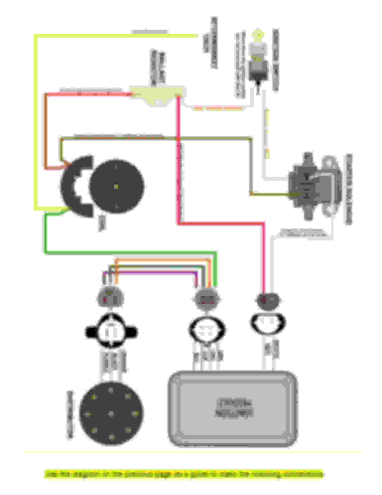
This is the diagram I am using for the new wiring harness:
It is showing both the red/grn coming from ballast resistor to the positive on the ignition coil, and the brown #970 ignition bypass coming from the same place.I currently have the ignition bypass coming off the positive from the ignition coil too. I think this is my problem. Should the brown be connected to the output of the resistor? That does not seem right to me.
This is the diagram that shows the red/grn and brown coming from the positive on the coil:
These are the instructions from the manual that made me think both of them should be connected to the positive.:
7.3.1 Connect ENGINE SECTION wire red/green #920 to one side of the ballast resistor. Using the remainder cut off of red/green #920; connect the other side of the ballast resistor to the positive post on the ignition coil. A ballast resistor is included in the parts kit. Be sure to mount it away from anything sensitive to heat, because it gets very hot. See Figure 7-8.
Note: During normal operation the ballast resistor gets very hot, be sure to mount it away from any other wiring.
7.3.2 Connect ENGINE SECTION wire brown #970 directly to the positive post on the ignition coil or the coil feed side on the ballast resistor. The other end is to be connected to the “I” terminal on the starter solenoid. See Figure 7-8.
Especially after reading what you said, this seems wrong. I am not exactly sure how? Should the red/grn be connected to the Start on the ignition switch? I understand the red/blue is the neutral safety switch. I do not have one, so I have bypassed by connecting the two wires together and have the red/blue connected to the I believe the start on the ignition switch. The other end connects to the S terminal on the starter solenoid. I know I am getting close, but haven't quite figured it out.
Like was said, ignition bypass #970 is hot only during cranking. It's actually an output from the solenoid feeding the ignition coil. If you want to see if this is your problem you can take it loose and try it. It's only there to give your spark a boost during cranking. You will not notice it much in warmer weather, only when it gets cold does it really help start the engine.
I hope you have more of a diagram than the above. The diagram you are using only shows the white wire going to the "s" terminal of the solenoid. That is correct, but you need another wire going to the "s" terminal to power the solenoid to power the starter. This is where the red/blue wire goes and comes from the ignition switch. Like the wire #970, the wht wire to the ignition module is just a starting aid, it will run without it. When the ignition module sees 12v on the white wire, it will retard the timing a set amount, this makes it easier for the starter to crank the engine over, especially in hot weather.
This is what I have looks like. This is a slightly old picture, but you can see the red/blue and white on the S terminal and the Brown on the I:
I am suspecting my problem is with the ballast resistor wiring. My manual shows that the red/grn goes from the fuse box to ballast resistor to coil +. This gives me red/grn and brown on the coil +. I am thinking the red/grn should go somewhere else, but I don't know where that would be? Maybe the red/grn should go to the coil and the brown to the same terminal of the ballast resist as the red/grn out? But I do not see how that would make a difference vs. being on the coil?
Do you have two problems? In your first post you mentioned when you hook the battery up it tries to start (cranking?). And you are also complaining that it will not shut off when you turn the key off?
A common problem that causes the symptom of not cutting off is when someone hooks all their ignition hots to one terminal on the ignition switch. This can cause problems sometimes from the "I" terminal of the regulator. The regulator/alternator can backfeed keeping 12v on the output of the ignition switch when the switch is turned off. Ford avoided this by having several different sections to the ignition switch, all working mechanically together but separated electrically.
What happened was when I reconnected the battery, it did not start until I turned the key. Then the truck turned over and started, but did not shut off. I had to disconnect the positive from the battery to shut it off. Now, when I connect the positive back it sparks and starts to crank. Once it starts, it does not shut off until I remove the red/grn from the ballast resistor or remove the positive from the battery. Hence why I put alternator backfeed in the title.
Originally Posted by lonewolf_
X2 ^^^^^ and the I terminal on the regulator isn't really needed any way
Thank you, that is a very useful diagram. I am starting to suspect the power wire that I thought was on ignition is constant. I will check tonight. If the wire going from the ignition to the red/grn is constant, that could be the problem. If there is alternator backfeed through the I terminal of the solenoid that could be the problem. Should be fairly easy to find out. Will let you know.
Went through all the wiring on the ignition switch. Went through all the diagrams and instructions I have. Made sure everything was wired correctly. Went to start on Tuesday, acted like the battery was drained. Figure since I had started it several times for short periods, it may not have recharged. Came on Saturday. Checked through everything again. Did not started. Slow crank, then dies. Dome light still comes on.
Used my other car to jump the battery. After several minutes, the truck still did not start. However, the jumper cables began to smoke, melt, and burn. Too hot to touch, I had to remove them with tools. Truck still does not start. I am very concerned that something bad is happening if wires are burning.
I am going to remove the power distribution block, and see if I can get it back at least to the point that it turns over. I am little concerned that I may have burned up my starter motor.
During the course of this, I found the new plug that connects the new harness to the ignition module red and white wires has a black ground on it. I do not think this is cause of my current problems, but no where do I see a ground coming from the red and white wires from the ignition module. I am guess this should be connected to ground? (see picture) I did try to connect it to the fender, but I think my other problems prevented me from telling if it did anything.
For reference I am including my ballast resistor and my ignition coil set-up to see if anyone else can see something wrong.
I put my voltmeter to the battery got 11.3V, then 7.6V a few days later. Brought the battery to be tested. 0mA. Charged until it got a reading, 263 of 725. Battery was bad. Replaced the battery. Removed the power distribution block, and the potentially offending amplifier cable.
Truck started and turned off normally, two times. Third time I let it run a little while to recharge the battery. This is when it started backfeeding through the alternator again. I have ordered a diode. My understanding is that this shouldn't be required, but I have been unable to find another cause of this problem. If there is one inside the alternator, it is the diode or a new alternator.
Further, I have had two different people tell me the burning of the jumper cables is due to a short. Currently, my biggest problem is where to begin to look for it.
probably crappy Jumper cables or hooked up backwards.... also if the cable connections are not good and Clean and you have a Flat battery the current draw can cause the cables to fry.... IF you had a short that was destroying Jumper cables then I'm pretty sure it would Blow Battery cables or battery too.
Rezvani's Latest Post-Apocalyptic Monster Is a Ford F-150 Raptor Underneath
Slideshow: Called the Fortress, the 850-horsepower pickup combines Raptor underpinnings with military-inspired features, survival equipment, and a starting price of $285,000.