When you click on links to various merchants on this site and make a purchase, this can result in this site earning a commission. Affiliate programs and affiliations include, but are not limited to, the eBay Partner Network.
it still don't look right ..... but yes the resistor is not Polarity specific.
So, I have the wires connected the opposite way when you look at it in the picture, the ignition bypass from the I terminal and the positive from the ignition coil are the left side of my picture. Plus the wire for the voltmeter. Yes, I felt skeevy connecting three wires to one spade terminal. However, if two work, so should three if it is just the voltmeter being added. I am going to switch their positions to reduce the tension on the wires.
I think I found my problem:
Remeber, this is why to use fuses and fusable links.
Ordered a new 70 Amp fuse from Amazon. Couldn't find one locally. I put a 30 in to test, and dome light comes back on. Haven't tried to start it yet. Will next weekend. Then on to the next obstacle.
I have been known to put multiple wires in a single terminal BUT I don't recommend it and I don't do it IF I can avoid it.
It's easy to find stackable terminals or 2 to 1 adapters, there are even Y and X terminals(3 way or 4 way) that are handy for splicing wires.
I've seen some really stupid crimps in my day too.... ie the image
Problem Solved. Pays to be able to use a voltmeter. Found the wire connected to the bat terminal was reading ~6v when the key was turned off. It was still backfeeding through the alternator. Removed the brown bypass wire from the I terminal on the solenoid. No change. Moved the black/ylw bat wire to start. This caused the engine to start when I connected the battery, not just when I turned the key. (This is not surprising if you think about it). Finally, I moved the blk/ylw bat wire to the other bat terminal on the ignition. Bingo, no more backfeeding and the engine shuts off when I turn the key to the off position. I still don't know why, because documentation says both are hot all the time.
Backfeeds on the horizontal bat terminal, but not the vertical one. The blk/ylw is the only wire connected either bat terminal.
We are a participant in the Amazon Services LLC Associates Program, an affiliate advertising program designed to provide a means for us to earn fees by linking to Amazon.com and affiliated sites.
What you did was separate the alternator from the ignition. If you have a simple one pole switch, one side of the pole is the battery, the other side (which would be "ign" terminal) the whole complete key on circuit for the entire vehicle would be hooked to that. That means the ignition circuit and the alternator circuit would be tied together (like they were). So when you turn the key off, they are still connected together and can interfere with each other.
Your switch is a double pole switch. You have 2 battery terminals, two ign terminals, two acc terminals. It's like two switches in one, mechanically connected but not connected electrically. So even though you jump the two battery terminals together and run them to the battery, the two ign terminals are being fed by their own set of contacts, the alternator and the ign are not connected together unless the key is turned on, then they are both connected to the battery. Turn the switch off, and they are on their own contacts now, and are not connected.
So how do I tell which set is on the battery and which is on the alternator? The battery terminals are the only ones not labelled 1 & 2. It makes sense to me that all the 1's would be on the same switch and all the 2's on the other. However, I am taking nothing for granted. I think I want the start and acc on the battery, but shouldn't the ignition be on the alternator?
There is no battery 1 and battery 2 reading the chart in your picture. They must be internally connected together. The chart says with the switch off, if you did a continuity reading, you will get no continuity between any of the terminals except the battery and the battery. That tells me they are connected permanently together. But why would it matter? The ignition switch's job is to connect things to the battery, so you do not need two different battery connections, not sure why they did that except maybe for amperage capacity.
The ignition connected to the alternator is exactly what your problem was. You want to keep them separate.
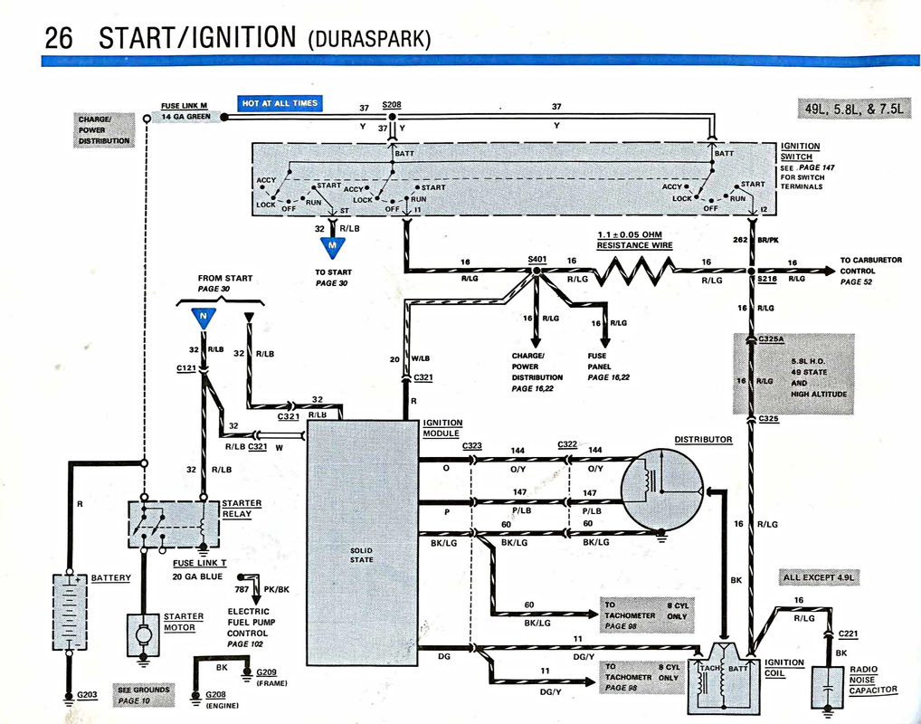
The picture below may explain it better. It's a diagram for a factory Ford 1986 ignition switch. It has 3 separate sections to it, while your switch only has two. You can see that ultimately all the switch below is doing is connecting things to the common battery terminals, so why have all those different sections? The reason? The diagram below shows the switch in the "lock" position. Notice how the blue power feed "M", the power feed "R/LG" and the power feed "BRN/PK" are all separate when the switch is in "lock". None of those different electrical circuits knows the others exist. So if the alternator is connected to one of those, and it happens to be generating power through it's exciter circuit, that power can't run up and back to the ignition when the switch is off if the ignition is hooked to a different circuit in the switch.
exactly, and in the above schematic the 3rd section of the switch on the far right is only used as the resistor Bypass... and you are using the 4 terminal Starter Relay for this function.
You see the one terminal Not connected on the Starter Relay could replace the 3rd section in the switch. on the above diagram.
And yes as Franklin2 says the 2 BAT terminals are internally wired together in the switch and is done so 2 smaller wires can be used instead of 1 Larger wire (for current Draw Reasons)
So I have my problem fixed. This is purely for my continued knowledge. That diagram helps. I feel I have wrapped my head around the double switch idea. What I don't understand is that if the two battery terminals are internally connected, why does one backfeed and not the other? Also, if the prevailing wisdom is that it is for amperage reasons, should run a second blk/ylw to the other bat terminal?
Last edited by Citymorg; Aug 19, 2019 at 05:39 PM.
Reason: Posting from my tablet
So I have my problem fixed. This is purely for my continued knowledge. That diagram helps. I feel I have wrapped my head around the double switch idea. What I don't understand is that if the two battery terminals are internally connected, why does one backfeed and not the other? Also, if the prevailing wisdom is that it is for amperage reasons, should run a second blk/ylw to the other bat terminal?
Both those battery terminals are the same. I am assuming since you asked your second question that you only have one wire going to one of the battery terminals. You can move that wire to the other battery terminal and it should work the same, those battery terminals are the same thing electrically. Since you asked this question I feel you haven't totally got your head wrapped around it, but you are getting close, keep asking questions.
As far as the double wire thing, that is all calculated out. I have lost track if this is a wiring harness you bought, or one you have made up yourself. But you have the capacity of the switch and it's individual sections, how much load each one can handle, how much load you actually have on it, and your wire size.
Off the top of my head I am going to say each part of the switch you have can handle 30 amps. What are the total loads of your circuits going through it? If they add up to about 30 amps, then one single 10 gauge wire feeding the switch would be sufficient. But if the total loads going through the switch add up to 50 amps, then you would use another wire in parallel, two 10 gauge wires to feed the switch side by side.
I think my problem is that because I get it I am confused about what I am seeing. I agree that if the two bat terminals are connected it shouldn't matter which one I use. I have a standard stereo with a 1000 amp and a dashcam. Other than that, the wiring is stock. I don't think I am going to draw over 30 amps at a time. (P.S.-part of the reason I am using a power distribution block is to run power straight to the amp off the battery).
I am using a Painless Wiring Harness for 1967-1977 trucks. I have a 1978. That explains some of the differences, but Painless was highly recommended and as close as I could get. (no fuse except the Maxi Fuse is rated over 30 amp)
Where I am running into problems is that I am backfeeding when I connect to one bat terminal, but not when I connect to the other. I would think it shouldn't matter, but it does. I would also think that I could run another wire from the Maxi Fuse (blk/ylw) to the other bat terminal to spread the amp load. I believe if I do that it will start backfeeding again. From the information I have, it makes sense that it is a double-switch with one being battery and the other being alternator. Therefore, I think they are not connected to each other, but each to one of the circuits. I just don't know, and have nothing to prove it other than what I am seeing.
P.S.-there are actually three wires coming out of the two terminals. One is a large (~10g) yellow wire. The other one has a similar yellow and a small red/ylw wire on it. Several positions on the plug have more than one wire coming off where there is only one terminal on the switch. I have only attached a minimum number of wires (bat, ign, acc, red/blu, and one power for a switched power block that only has an aftermarket tach on it.)
Interesting. You mentioned what wiring you had, so I went to their website. Downloaded the manual. There is no diagram for your wiring harness. That have little snippets of different components and different sections, but no full complete wiring diagram of the harness they sell. I am not impressed.
Interesting. You mentioned what wiring you had, so I went to their website. Downloaded the manual. There is no diagram for your wiring harness. That have little snippets of different components and different sections, but no full complete wiring diagram of the harness they sell. I am not impressed.
I have been using that .pdf/book that came with it. I also have the Chilton book that does have a pretty good wiring diagram of the entire truck, and I used this website https://www.americanautowire.com/PDF...20IN%200.0.pdf to wire the instrument panel. Which by the way seems to be slightly jacked up too. I know it is American Wire and not Painless, but it was the information I needed to figure out which pin which wire was supposed to go.
Right now, the wiring works, headlights, tailights, turn signals, reverse lights etc. When I plug in the instrument panel, the right blinker does not come on in the instrument panel, even though it is blinking outside the truck. It also blinks fast when it does not when the instrument panel is not attached. Further, the lights on the panel do not come on when I turn the headlights. Just the next rabbit hole for me to go down. I did replace the circuit board, when I plug it in, the flap got pushed in and scrunched a little bit. I do not know if it is completely ruined.
I have fixed many of those scrunched places where the plug goes in. Get something to carefully flatten the copper back out, then put a small dab of superglue on the back of the copper and push it down onto the clear mylar where it belongs. Hold it there for a minute or two and let it dry, and it will be good as new.
So I dropped the gas tank to fix the float, and make sure the wiring on the sending unit is right for the gas gauge to work. (probably unrelated, but that is the last change I made)
At the same time, I connected ignition switch and found a loose wire in the turn signal harness. The green wire had come disconnected. I bypassed it and connected it directly to the wire on the other side.
Now when I try to start the truck, even with a full charged battery, it drains the power out of the battery (goes from ~13V down to 7-9V) as soon as I connect the red and black wires before cranking on the engine. As soon as I connect the battery terminals the distributor starts clicking. Further, when I turn the key, it starts cranking but will still backfeed through the alternator and continue cranking after the key is removed. In this state the truck no longer turns over and starts.
Rezvani's Latest Post-Apocalyptic Monster Is a Ford F-150 Raptor Underneath
Slideshow: Called the Fortress, the 850-horsepower pickup combines Raptor underpinnings with military-inspired features, survival equipment, and a starting price of $285,000.