
Transmission, pull / install notes

Thread Starter
|
Tuned


Joined: Aug 2009
Posts: 402
Likes: 16
Transmission, pull / install notes
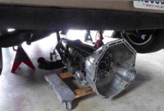
This example shows an A4LD tranny mated to a 3L engine.
The 4R/5R electronic trannies will be 98% similar with the exception of the modulator line and the harness connections for sensing & control.
The bell housing will differ between 3L and 4L engine apps .
This procedure can be used for both pulling and installation.
At any point where installation is not the exact opposite of pulling, the relevant installation procedure is provided.
A top mechanic on game day can get each direction done in 90 minutes, perhaps less.
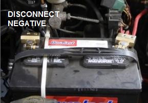
******* Battery ************
Battery should be disconnected, although there are no immediate consequences.
Worst case, the starter cable is touching the frame while someone attempts to start.
Smart protocol has one disconnecting the negative side, because a wrench from the negative terminal to chassis will do no harm.
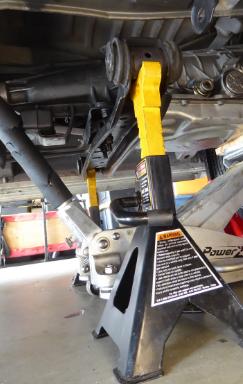
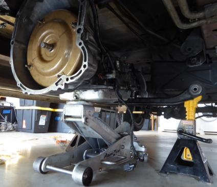
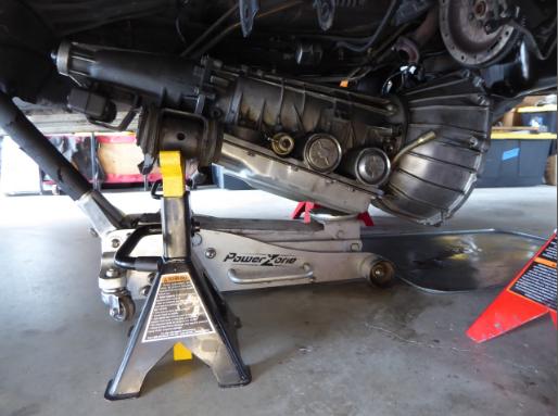
*** Vehicle jacking ***
Low profile floor jack at front suspension subframe.
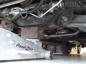
Jackstands are placed at the cross spars.
We use 3 tons (each), mostly because of the height that comes with the rating.
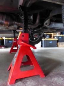
Height required due to clearance needed during roll out.
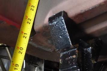
21-1/2inches shown but we could probably get away with 20.
Sneek preview showing clearance to bumper etc.
*** Fluid ***
We would like the level of fluid reduced, to minimize spills and weight.
The original pan does not include a drain port and therefore the transmission can only be draining by unbolting the pan and cascading the fluid into a catch bin.
Pan bolts: 13mm std with 4" extension.
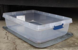
This particular transmission has had a drain port retrofitted, therefore we have the option of using a smaller bucket and we don't need to spend time and effort on the numerous bolts.
Regardless of which method is used, a substantial quantity of fluid is left trapped inside and will be released at inconvenient times as the transmission is moved, tilted and disassembled.
*** Driveshaft ***
1/2 inch box wrench
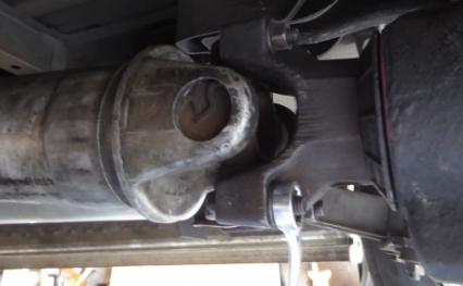
A small amount of fluid can be released from the tail.
This tends to be a problem only if the transmission has not been emptied and the unit is tilted down at the rear.
*** Support tranny ***
Place the floor jack to the rear with the lifting pad supporting near the front edge of the pan.
This support point gives a slight tail heavy bias.
*** Cross member removal ***
We need to temporarily remove the tail support aka cross member.
19mm deep socket for tranny tail nuts
15mm deep socket & 13mm std for side bolts
Note: although a wood block shows up in this great pic, we don't use a block because the transmission might slip off.
Instead the jack's pad is put directly against the pan.
The pad has a lip that wraps around the edge of the pan, resisting it from sliding off.
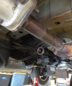
*** Exhaust ***
This allows for access to the cooler port
15mm , 10" extension
When restoring nuts, high temp anti-sieze
*** Cross member restore & support ***
After removing exhaust, re-attach crossmember to the tranny tail, but not the Aero chassis.
Then place a set of jackstands under the left and right ends of the crossmember.
This is to provide side-to-side balance control as the tranny is lowered by the floorjack.
Note: although a convenient balance bar, it does block the push-back procedure.
Note to self: It would be nice to have a shorter balance bar, or one that curves down or back.
In no particular order, remove connections...
*** Filler tube ***
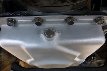
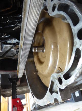
*** Torque Converter - flexplate nuts ***
Flexplate cover (not shown), 10mm std socket.
The torque converter is fastened to the flexplate (attached to the engine crankshaft) by nuts screwed onto studs, 4 places around the converter.
Qty 4 nuts, 14mm socket with long extension.
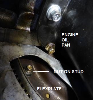
Each nut is made visible in a service window by rotating the engine a quarter turn.
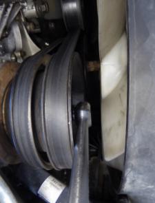
21mm deep socket with short extension, applied to the crank bolt at the front of the engine.
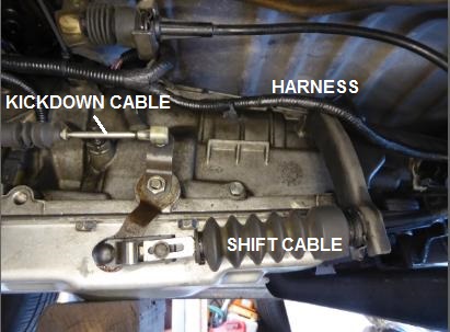
*** Harness & shifter ***
The harness connects to the A4LD at 3 places.
The shifter cable comes in low, from the rear.
The A4LD has another cable coming in high, from the front, (probably) handling the kickdown input.
Both these cables terminate in ball joints that snap off, snap on.
The shifter cable is also anchored to a bracket with a clip that slides out, releasing the cable.
All harness and cables are tucked above, out of the way.
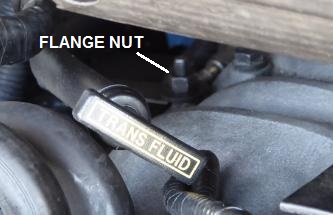
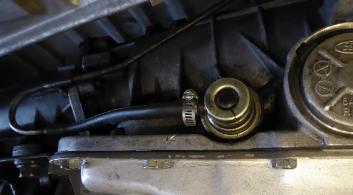
*** Vac mod line ***
The A4LD has a vacuum modulation tube.
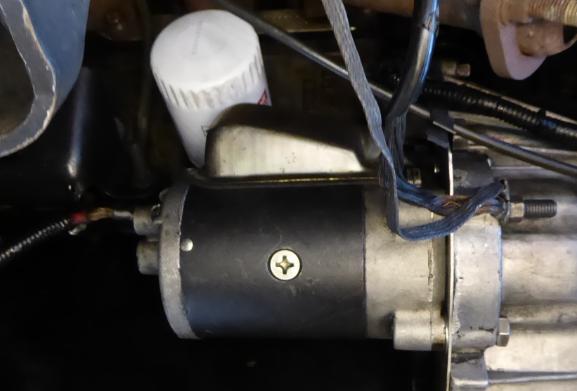
*** Starter ***
Battery has already been disconnected.
Gnd straps on bolt, 13mm deep socket.
Remaining bolts were 15mm standard with short-med extension.
The positive cable is removed so that the heavy starter is not left dangling. 10mm or 3/8in std socket.
*** Cooler lines ***
5/8in box wrench.
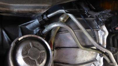
Remove the bracket at engine.
This allows the ends to float around a bit and not get bound up.
This flexibility is especially important during installation.
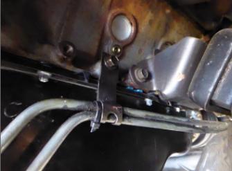
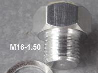
Ports will weap fluid endlessly, coming from the torque converter.
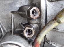
...unless plugged.
Note: that the port has been adapted, therefore the thread spec could vary by application.
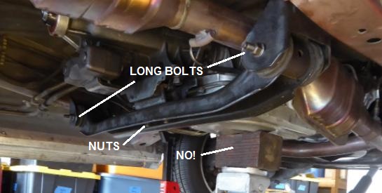
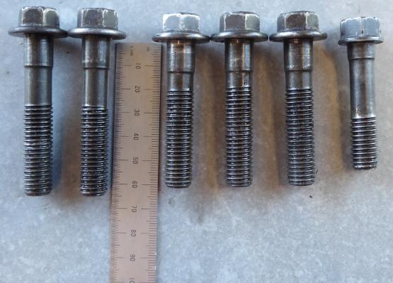
*** Engine bolts ***
2 at top, accessible from the passenger compartment.
2 each side.
3 starter bolts, not shown here.
Typically, slightly longer bolts are used into aluminum, while slightly short bolt is used into iron (threads on engine side).
*** Pull back ***
After removing bolts, nuts & lines, begin shifting the tranny rearward.
The initial separation occurs with little effort, so if there is any resistance to separation, re-check for remaining connections.
Very soon afterward the cross member will get trapped by the connection brackets on the frame, and therefore will need to be lowered to clear these.
Then rearward migration can proceed further.
As the transmission and supporting floorjack are moved rearward, the jackstands supporting the cross member also need to slide back.
Note that the (3.0L) engine is almost balanced on its mounts and needs no further support from a jackstand.
This is convenient because, after lowering the transmission, we will be rolling it forward to exit and an engine support stand would block the way.
Fyi, without the tranny to level it, the engine will tilt down to the rear.
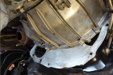
In between the engine and transmission is a sheetmetal plate.
This can be removed as soon as we have clearance away from the bolthole sleeves that would otherwise trap the plate.
As the transmission migrates rearward, it will eventually collide with the tunnel, and therefore will need to be lowered, by both the floor jack and the jack stands supporting the cross member.
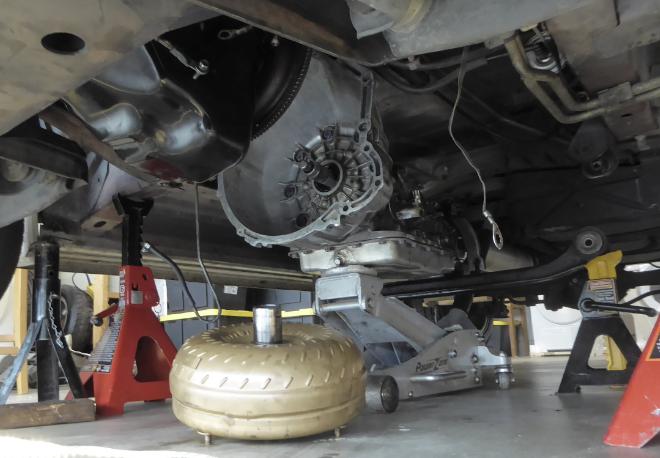
Eventually, enough clearance is gained between transmission and engine to extract the torque converter.
We remove the torque converter now because when we soon tilt the front of the transmission downward, it will otherwise slide forward and crash to the floor.
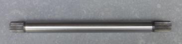
Same story the input shaft. Remove it now or it slides out at an inconvenient time.
Note that the converter is filled with fluid and that the rear port should always be level or tilted up to avoid spills.
*** Installation note: Torque converter ***
Here, installation is not the mirror of extraction.
Skill and method is required to fully seat the converter back into the bellhousing.
How NOT to do it: first install the input shaft into the transmission, then slide the converter into place.
The problem with this sequence is that the input shaft, already installed into the transmission, will rarely seat fully into the converter as it is later pushed in.
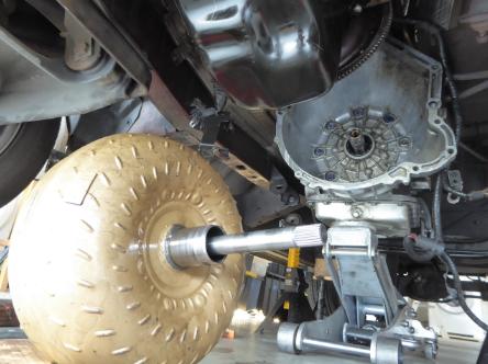
Instead, first seat the input shaft into the converter then slide the combination into the transmission.
BE VERY CAREFUL to support the TC, centered, as you get the input shaft started into the hole.
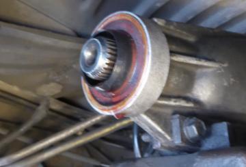
Note that the the pump just inside the transmission has flats along the input shaft.
These can be seen by staring along the outside of the shaft, into the pump.
Note: we know this pic is from a 4R/5R pump and not from an A4LD because the A4 lacks the o-ring seal.
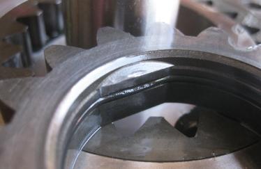
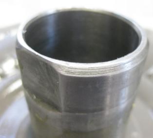
Corresponding flats are found on the torque converter, at the rear.
Therefore, in order to seat, the converter must be clocked to align with the pump.
Hint: mark the front side to indicate the clocking of the flats.
When seated correctly the pilot shaft sits approximately 1/2in below the bellhousing.
In this case the converter glides into the crankshaft with little effort.
If however the converter gets caught on the end of the input shaft, and is therefore NOT seated correctly, then the converter pilot will sit approximately a 1/2in proud of the bellhousing.
Seriously, DO NOT attempt to bolt the transmission to the engine unless this spec is met.
You would not be successful and you would bend things.
During installation, as the transmission is moved into position, the torque converter should be clocked so that its studs pass thru the associated holes in the flexplate.
The option is to either turn the TC with fingertips or turn the engine using the 21mm socket applied to the crank bolt at the front.
Spacer plate is pushed onto bolt hole sleeves, each side.
**** Back to extraction procedure ****
Place blocks (not shown) under the bellhousing and lower the floor jack until it can be extracted.
Using personal strength lift the bellhousing and slide a cart under.
Place the floor jack under the cross member and lift the tail off the jack stands.
Then lower the tail.
Roll out.
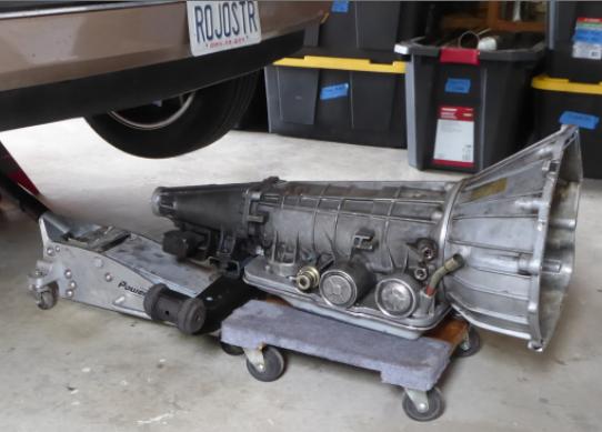
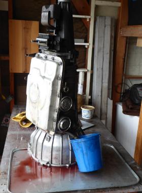
*** Drain fluid via fill port ***
The transmission still contains a significant amount of fluid and this will gush out the filler hole when the transmission is tilted forward.
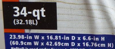
Be prepared with a small tall bucket to receive up to a liter of fluid.
Note that with the converter and crossmember removed, the remaining transmission weighs about 100 lbs.
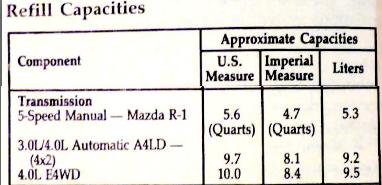
*** Fluid fill ***
After overhaul the transmission & TC combined will take approximately 8 liters or 2 gallons of fluid.
The smart procedure is to start with a low level under-fill, then increase until proper operation is achieved.
Note: The tranny dipstick is notoriously difficult to read and it may also lack proper calibration.
Therefore you might find that a proper fill level requires taking the visual indication under advisement but fill to whatever eventually gives proper operation.
Engine must be on, otherwise reads too high.
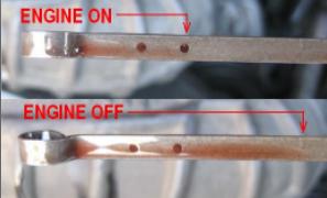
Transmission and TC must be warmed up, otherwise reads too low.
Typically this requires that the vehicle be driven, at least a short distance.
Therefore an iterative process is followed.
First put in enough to drive, noting that the engine might need to be rev'd and engagement is a sudden jerk.
If so then adjust the level upward by about 1/2 to 3/4 liter.
Note that unless you have retrofitted a drain plug, extracting an over fill is difficult.
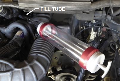
Extraction could be achieved via the fill tube using a suction gun and long hose.
The 4R/5R electronic trannies will be 98% similar with the exception of the modulator line and the harness connections for sensing & control.
The bell housing will differ between 3L and 4L engine apps .
This procedure can be used for both pulling and installation.
At any point where installation is not the exact opposite of pulling, the relevant installation procedure is provided.
A top mechanic on game day can get each direction done in 90 minutes, perhaps less.
******* Battery ************
Battery should be disconnected, although there are no immediate consequences.
Worst case, the starter cable is touching the frame while someone attempts to start.
Smart protocol has one disconnecting the negative side, because a wrench from the negative terminal to chassis will do no harm.
*** Vehicle jacking ***
Low profile floor jack at front suspension subframe.
Jackstands are placed at the cross spars.
We use 3 tons (each), mostly because of the height that comes with the rating.
Height required due to clearance needed during roll out.
21-1/2inches shown but we could probably get away with 20.
Sneek preview showing clearance to bumper etc.
*** Fluid ***
We would like the level of fluid reduced, to minimize spills and weight.
The original pan does not include a drain port and therefore the transmission can only be draining by unbolting the pan and cascading the fluid into a catch bin.
Pan bolts: 13mm std with 4" extension.
This particular transmission has had a drain port retrofitted, therefore we have the option of using a smaller bucket and we don't need to spend time and effort on the numerous bolts.
Regardless of which method is used, a substantial quantity of fluid is left trapped inside and will be released at inconvenient times as the transmission is moved, tilted and disassembled.
*** Driveshaft ***
1/2 inch box wrench
A small amount of fluid can be released from the tail.
This tends to be a problem only if the transmission has not been emptied and the unit is tilted down at the rear.
*** Support tranny ***
Place the floor jack to the rear with the lifting pad supporting near the front edge of the pan.
This support point gives a slight tail heavy bias.
*** Cross member removal ***
We need to temporarily remove the tail support aka cross member.
19mm deep socket for tranny tail nuts
15mm deep socket & 13mm std for side bolts
Note: although a wood block shows up in this great pic, we don't use a block because the transmission might slip off.
Instead the jack's pad is put directly against the pan.
The pad has a lip that wraps around the edge of the pan, resisting it from sliding off.
*** Exhaust ***
This allows for access to the cooler port
15mm , 10" extension
When restoring nuts, high temp anti-sieze
*** Cross member restore & support ***
After removing exhaust, re-attach crossmember to the tranny tail, but not the Aero chassis.
Then place a set of jackstands under the left and right ends of the crossmember.
This is to provide side-to-side balance control as the tranny is lowered by the floorjack.
Note: although a convenient balance bar, it does block the push-back procedure.
Note to self: It would be nice to have a shorter balance bar, or one that curves down or back.
In no particular order, remove connections...
*** Filler tube ***
*** Torque Converter - flexplate nuts ***
Flexplate cover (not shown), 10mm std socket.
The torque converter is fastened to the flexplate (attached to the engine crankshaft) by nuts screwed onto studs, 4 places around the converter.
Qty 4 nuts, 14mm socket with long extension.
Each nut is made visible in a service window by rotating the engine a quarter turn.
21mm deep socket with short extension, applied to the crank bolt at the front of the engine.
*** Harness & shifter ***
The harness connects to the A4LD at 3 places.
The shifter cable comes in low, from the rear.
The A4LD has another cable coming in high, from the front, (probably) handling the kickdown input.
Both these cables terminate in ball joints that snap off, snap on.
The shifter cable is also anchored to a bracket with a clip that slides out, releasing the cable.
All harness and cables are tucked above, out of the way.
*** Vac mod line ***
The A4LD has a vacuum modulation tube.
*** Starter ***
Battery has already been disconnected.
Gnd straps on bolt, 13mm deep socket.
Remaining bolts were 15mm standard with short-med extension.
The positive cable is removed so that the heavy starter is not left dangling. 10mm or 3/8in std socket.
*** Cooler lines ***
5/8in box wrench.
Remove the bracket at engine.
This allows the ends to float around a bit and not get bound up.
This flexibility is especially important during installation.
Ports will weap fluid endlessly, coming from the torque converter.
...unless plugged.
Note: that the port has been adapted, therefore the thread spec could vary by application.
*** Engine bolts ***
2 at top, accessible from the passenger compartment.
2 each side.
3 starter bolts, not shown here.
Typically, slightly longer bolts are used into aluminum, while slightly short bolt is used into iron (threads on engine side).
*** Pull back ***
After removing bolts, nuts & lines, begin shifting the tranny rearward.
The initial separation occurs with little effort, so if there is any resistance to separation, re-check for remaining connections.
Very soon afterward the cross member will get trapped by the connection brackets on the frame, and therefore will need to be lowered to clear these.
Then rearward migration can proceed further.
As the transmission and supporting floorjack are moved rearward, the jackstands supporting the cross member also need to slide back.
Note that the (3.0L) engine is almost balanced on its mounts and needs no further support from a jackstand.
This is convenient because, after lowering the transmission, we will be rolling it forward to exit and an engine support stand would block the way.
Fyi, without the tranny to level it, the engine will tilt down to the rear.
In between the engine and transmission is a sheetmetal plate.
This can be removed as soon as we have clearance away from the bolthole sleeves that would otherwise trap the plate.
As the transmission migrates rearward, it will eventually collide with the tunnel, and therefore will need to be lowered, by both the floor jack and the jack stands supporting the cross member.
Eventually, enough clearance is gained between transmission and engine to extract the torque converter.
We remove the torque converter now because when we soon tilt the front of the transmission downward, it will otherwise slide forward and crash to the floor.
Same story the input shaft. Remove it now or it slides out at an inconvenient time.
Note that the converter is filled with fluid and that the rear port should always be level or tilted up to avoid spills.
*** Installation note: Torque converter ***
Here, installation is not the mirror of extraction.
Skill and method is required to fully seat the converter back into the bellhousing.
How NOT to do it: first install the input shaft into the transmission, then slide the converter into place.
The problem with this sequence is that the input shaft, already installed into the transmission, will rarely seat fully into the converter as it is later pushed in.
Instead, first seat the input shaft into the converter then slide the combination into the transmission.
BE VERY CAREFUL to support the TC, centered, as you get the input shaft started into the hole.
Note that the the pump just inside the transmission has flats along the input shaft.
These can be seen by staring along the outside of the shaft, into the pump.
Note: we know this pic is from a 4R/5R pump and not from an A4LD because the A4 lacks the o-ring seal.
Corresponding flats are found on the torque converter, at the rear.
Therefore, in order to seat, the converter must be clocked to align with the pump.
Hint: mark the front side to indicate the clocking of the flats.
When seated correctly the pilot shaft sits approximately 1/2in below the bellhousing.
In this case the converter glides into the crankshaft with little effort.
If however the converter gets caught on the end of the input shaft, and is therefore NOT seated correctly, then the converter pilot will sit approximately a 1/2in proud of the bellhousing.
Seriously, DO NOT attempt to bolt the transmission to the engine unless this spec is met.
You would not be successful and you would bend things.
During installation, as the transmission is moved into position, the torque converter should be clocked so that its studs pass thru the associated holes in the flexplate.
The option is to either turn the TC with fingertips or turn the engine using the 21mm socket applied to the crank bolt at the front.
Spacer plate is pushed onto bolt hole sleeves, each side.
**** Back to extraction procedure ****
Place blocks (not shown) under the bellhousing and lower the floor jack until it can be extracted.
Using personal strength lift the bellhousing and slide a cart under.
Place the floor jack under the cross member and lift the tail off the jack stands.
Then lower the tail.
Roll out.
*** Drain fluid via fill port ***
The transmission still contains a significant amount of fluid and this will gush out the filler hole when the transmission is tilted forward.
Be prepared with a small tall bucket to receive up to a liter of fluid.
Note that with the converter and crossmember removed, the remaining transmission weighs about 100 lbs.
*** Fluid fill ***
After overhaul the transmission & TC combined will take approximately 8 liters or 2 gallons of fluid.
The smart procedure is to start with a low level under-fill, then increase until proper operation is achieved.
Note: The tranny dipstick is notoriously difficult to read and it may also lack proper calibration.
Therefore you might find that a proper fill level requires taking the visual indication under advisement but fill to whatever eventually gives proper operation.
Engine must be on, otherwise reads too high.
Transmission and TC must be warmed up, otherwise reads too low.
Typically this requires that the vehicle be driven, at least a short distance.
Therefore an iterative process is followed.
First put in enough to drive, noting that the engine might need to be rev'd and engagement is a sudden jerk.
If so then adjust the level upward by about 1/2 to 3/4 liter.
Note that unless you have retrofitted a drain plug, extracting an over fill is difficult.
Extraction could be achieved via the fill tube using a suction gun and long hose.

Lead Driver

Joined: Sep 2003
Posts: 7,015
Likes: 208
From: SoCal

One of the Ford transmission engineers on that forum told of a time when he was developing a transmission for a Taurus, and had to swap out the transmissions a couple times throughout the tests. He said a couple of technicians did the swap in about 45 minutes each time.

Thread
Thread Starter
Forum
Replies
Last Post
Messmoss
1973 - 1979 F-100 & Larger F-Series Trucks
10
Oct 19, 2018 06:43 PM
aussie_f350
1999 - 2003 7.3L Power Stroke Diesel
2
Jan 21, 2013 03:47 PM
takotruckin
1999 - 2003 7.3L Power Stroke Diesel
19
Sep 21, 2010 07:35 PM


