When you click on links to various merchants on this site and make a purchase, this can result in this site earning a commission. Affiliate programs and affiliations include, but are not limited to, the eBay Partner Network.
I know there have been discussions about alternators and wiring and the things to look for, but those conversations have always been part of other threads. then the threads i did find pertaining to alternators were really about something else, or one very specific issue. so what i would like to do is have a thread about how they work, how to test them, what things can go wrong and what symptoms to look for. I am not the expert on this, i just want to get the ball rolling so that we can have an easily searchable thread with good info for everyone. i also have an issue with mine at the moment that I am hoping this discussion will help clear up.
i will start with what i know, and how i got there.
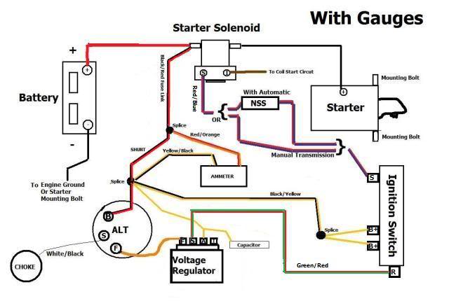
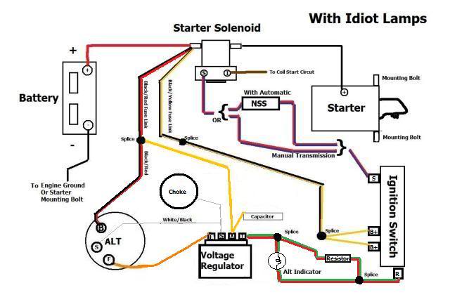
Bam! Updated. �A� is the battery voltage to the regulator taken directly off the lead going from alternator to battery.
I borrowed these from the other websites where i found discussions about alternators. Maybe these have made their way on here before, but I couldnt find them.
These were the basic diagrams that helped me understand what I was looking at, how it was all connected, and what was initially wrong with my setup. It didnt really help me understand how it worked, or why my system still isnt working.
A bit about what i found with my set up and what that led me to:
My battery died. I put the battery on the charger overnight, put it back in the truck, checked voltage with engine off ( 12.7, just right). Started the truck and tested between the battery posts (12.1, not good). the battery voltage will drop a bit during start up and while running because there is power being drawn from it, so the voltage goes down a bit. But when the truck is running there should be around 14 volts measured between the battery posts. this is because your alternator should be adding more voltage (amps are more important at this point, but semantics). Anything higher than the voltage you measured with the engine off means there is something coming from the alternator. Anything less than means nothing coming from alternator.
The simple things to check are the alternator itself which unbolts fairly easily, take it to a parts store, they will test it. Doesnt mean the thing is 100%, and if you are questioning whether that test was 'correct' take it to another shop with another machine and see what theirs says. If you alternator is bench tested as outputting 14 ish volts and close to the correct amps for its size its ok. It still might be good to replace it, you are already there, its already out, they arent that expensive. Up to you. BTW all this sage advice is only what i am compiling from the great many sources I used on my journey.
If you think your Alt is good, or you want to start with the simpler things first (like i did) we can check the voltage regulator. Mine looked like garbage, was the original mechanical style, and there was some discoloration on the backside so i just replaced it. Only like $10 for a new solid-state one. Now for my first question that someone else can hopefully answer. Solid state vs mechanical: are there any instances where this would matter for making your alternator work?
A better way to actually TEST your voltage regulator is to jumper the F wire (field wire, sometimes its orange) to the A (sense wire input). you do this with the connector removed from the external regulator. You can do this with the engine running, but if you are squeamish about getting zapped add the jumper with the IGN off then start the truck. With the jumper in place you are bypassing the regulator and forcing the alternator to make power. Now measure the voltage across the battery terminals. If there is more voltage there now, you regulator is suspect, but not 100% confirmed bad. I did not do this test because i bought a new regulator, but turns out this test also tests whether your ground circuit for your alt is good, and whether it will make power based on the v-belt rotation, and its current situation in the vehicle. so i should have done this test as well, and will as soon as I get home from work.
The next step is to test the inputs to the regulator. there are really only two. The constant voltage from the battery, and the keyed-on power from the ignition switch. With the Key on but not running there should be Battery voltage, whatever that is at the moment, on two of the connectors for the regulator. One of those is coming directly from the battery, and the other is coming from the ignition switch. If you are missing one of those, something is wrong. Mine was wrong so i had to go find it. Mine was because the ignition switch was wired WRONG, so wrong. But i figured it out and you can too. Use the diagrams all over the internet, follow the wires, seperate the looms, trace them out. Here is where we need some more expertise. with the key on but not running there should also be some voltage (3 ish?) on either the Field or Stator wire? That voltage is basically showing you that the alternator is 'primed and ready.' but if you dont get this voltage it wont be charging when you do start the engine.
the next step is to confirm your wiring. I figured out the wire that goes from the ALT to the battery was open/broken/not connected. I did this by removing the battery terminals and checking for resistance between the + battery lead and the 'A' alternator input at the regulator. When that was no good i went between the starter solenoid and the regulator 'A.' and when that was no good I took the wiring out and went through the whole thing. I wish i had a picture of what was done before, but it was garbage. Fixed all that and since I had to remove the Alt to remove the wires anyway, i took it to the store to get tested. they ran it three times and it showed good voltage and good current (amps). so i figured it must have been because of the garbage soldering on the charge cable that my system was not working and that once i put it all back in it would work. I had picked up a new V-belt while i was at the store since the old one was rotten. turns out i have to tell the clerk that my truck is an F100 (even though it is DEFINITELY a 250) in order to get most of my parts correct the first time. Got the right belt, installed the Alt and new belt, tightened everything up and started the truck. Still no voltage from the alt. But this time I have all the correct voltages going to the regulator. So why no worky-worky?
i did some more digging around.
I have an alt-light (dummy light) set up. Maybe the wiring was set up for an alt gage? removed the Alt again to confirm the connections on the back were in the right spot and to confirm they match the Alt-light set up for my truck. yup, checks out. What i mean is pay attention to where your Constant voltage and keyed voltage are going into your regulator, and where those wires are ending up on the back of the Alt.
So more digging. I read that the voltage regulator needs to be able to compare the voltage the battery has to the voltage that the system is sending back to the regulator (testing how much power is lost after it goes through some other systems). that this comparison is what tells the alternator to start charging. So i went back under the dash to try to figure it out. Everything i read said that the dummy light was vital to the charging system, that it would not charge without the light installed. UNLESS, there is a resistance wire in parallel to that light curcuit. So i had to find out if this was the case. this lead me to remove most of the electrical tape that was the 'wire looming' under the dash. I then traced the purple resistance wire from where it starts in the ignition switch all the way to the connector near the glove compartment where it meets up with its counterpart the green/red wire from the alt light. It was all in place and resistance from that wire all the way to the regulator was good. Good as in it was not broken/open, but could it be too good? not enough resistance? No because the light is coming on which means that part of the circuit is good. I also figured out why this is so important. If there is no light bulb, or the bulb has burnt out the circuit is broken, meaning that start-up power isnt getting to the regulator. and the resistance wire just gives another route for that power to get there if the bulb is blown or missing. As long as the Alt light comes on while the key is on but not running, and then goes out after its running your system is good. If the light comes on but doesnt turn off after running you at least know power is getting to the regulator through that curcuit.
more digging. how does the light turn on, and then how does it turn off. This is where my electrical training came in handy. If you are applying power to the alt light it has to have somewhere to go in order to actually turn on the light. the power has to flow. So where is the flow going? turns out it flows into the voltage regulator. So if the light turns on (in ACC) the regulator has power. NOW, how does it turn off? Well, once the alternator is making power the voltage regulator doesnt just remove the ground to turn off the light, because that would interupt the alternator circuit and turn it back off. the regulator actually sends power back the way it came. This is basically like two rivers meeting. If they both have the same amount of force the flow will stop. this is what happens with the light. Once the Alt makes power it turns off the light by sending more power to it but from the opposite direction. (head=blown emoji).
That brings me to the reason for this whole write-up, and hopefully you like what ive started and some of you can add more intelligent thoughts/wisdoms to make it worth reading. While researching this again i realized i never tested to see if jumpering power straight to the alternator would make it turn on. I didnt think i needed to because i had already bought a new regulator. but then i thought, if all the power is getting to the regulator, and none of the power is getting out of the regulator, maybe the problem is the regulator!! I should know better than to trust "new" parts.
Im a CIWS technician in the Navy, I once had to order a $300 part basically overnight super-express shipping mode because we wanted to shoot the gun the next week. Part arrived just in time, installed, still didnt work. Months of troubleshooting, thousands of dollars spent trying to fix it, experts from across the country, nobody could figure out what was wrong. Thats when i got the bright idea to step back and look at the whole picture like you do when a problem first happens. Turns out the $300 part we got new was worse than the broken part we removed. Installed a good one and got to shoot down a simulated missile the next week. Moral: dont trust new parts, test them too.
Lets just say that my voltage regulator isnt bad. What else should i, and anyone else with this type of issue, be looking for and how can we test to eliminate things?
I confirmed what I suspected. First: When the regulator is unplugged the alt light does not light with key switched on. This means there is not a ground where there shouldn�t be in this circuit. It also confirms that the voltage is getting to the regulator. Second: with F and A jumpered the Alt does indeed make voltage. Battery volts jumped up to 16. Was 13 after a full charge.
Now for some more findings and questions. With the regulator connected I have Bat Volts on A, as it should be, zero volts on the Sense wire (also I think as it should be zero until after Alt starts making juice), but I only have 6.3 volts on the red-green Keyed ignition wire from the alt light. I think this is correct, because once the voltage is being drawn the resistance through the light should drop the measured voltage. Can anyone confirm those numbers?
Also a piece of info that might be relevant: the alt light is lit, but it is rather dim. As in during daylight, and before I swapped the instrument cluster lens for a clear one I could barely tell it was on. Now it�s pretty clear it�s on but it is still very dim.
my suspicion is still that the �new� regulator is bad. I will get a new one next time I am at the parts store. But if that sense wire is supposed to have some voltage on it while running maybe there IS something wrong with the Alt itself. Thanks for the help everyone.
A great write up! (I rep'ed you for it.) IF, all the wiring is in the correct places (and in good shape) then Normally the dim light should signal that the output (from the alternator) is too low.. BUT, I don't know if the use of the solid state regulator is fully compatible with the other old style components and your current wire routing or not.
Well I was right. The solid state voltage regulator was either not compatible or was no good from the store. Either way finally got the mechanical type from the store and as soon as it was hooked up everything was grand. Reading about 15.5 volts while running. I think that might be a bit high, and maybe this mechanical type is adjustable. I will check next time. For now I�m just glad it�s working. Btw the one I installed was a Standard Products. I saw a thread about their products. I will see if this one craps out.
The only down side to mechanical vice solid state is that I can hear it click every time it turns on and off. Which at idle is basically once every second. This might also because it�s trying to charge too high and needs adjusting. It also might be the drawback to a Standard Products part. It�s also MUCH bigger (taller?) than the original. Hopefully that means it is sturdy.
Those diagrams have one fault that could be a problem. The "A" wire is never from the ignition switch.
Only the "I" wire (with light) or the "S" wire (with ammeter) are powered through the ignition switch.
In theory there is nothing wrong with using the switch to send a signal to the A circuit, but in reality there is too much voltage drop between. And the regulator needs to read the BATTERY voltage as accurately as possible. Hence it being spliced directly to the battery power wire to the cabin, or somewhere similar so that it gets as direct a reading off of the battery as is reasonable per the Ford designer's criteria.
If it's attached to a switched wire, especially one that feeds other circuits, it might think the battery is in a constant state of under-charge, and keep the alternator pumping out the juice to keep it topped off when it does not need to be.
And yes, your 15.5v is too high. I don't know if that is in the "don't do it" zone yet or not. Just that 14.5v is usually optimal according to most Ford specifications. In my experience there is a sweet spot AND an allowable range. But I don't know what the official range is.
I do know that if you see over 16v you should be figuring it out right away before your battery suffers.
As "1TonBasecamp" said 15.5 is a bit too high. Unless your battery is low, and the system was just charging it up when you took the reading. Watch it very closely and see it the charging voltage starts to drop. If it doesn't be aware that the battery may start to boil or explode from the heat and pressure.
i thought 15 was too high. When the engine warmed up and it dropped to curb idle the regulator was clicking a lot and the voltage was jumping from about 16.1-15.4V. I only have a digital multimeter so this was poorly showing the fluctuation as the switch turns the ALT on and off. I think these mechanical ones are adustable so I will pull it back out and check. I am wondering if the greater voltage is because the battery had come off an external charger and was already charged to around 13.5. I guess i will keep working on it.
Might have a defective mechanical regulator too. I'm surprised you can even still find one, but it's almost a guarantee it's built overseas just like most everything else.
I never had any trouble updating to the electronic regulators on any of my vehicles.
But speaking generically regarding your wiring, how are your grounds? Is the regulator grounded? Is there still a ground wire running between the alternator and one of the screws that attaches the regulator to the body?
Do you still have a body ground? Where is your engine ground?
Whenever updating, upgrading, or modifying your electrical and charging systems, it's not a bad idea to not only verify your existing grounds are sound, but to add a couple more!
Upgrade to new battery and starter cables of at least a slightly larger gauge.
Clean and tighten connection points.
If they're not already existing, add ground wires, or straps from the battery negative to the body, and from the engine to the body (usually back of intake-to-firewall) and even follow Ford's own practice on later model trucks of bonding the body/cab to the frame with braided grounding straps bypassing the rubber body insulators at the frame mounts.
Even if you go all animal on it and throw extra wires in all sorts of spots, there really is no such thing as too many grounds. Especially on an old vehicle like ours where many of the panels that used to ground to each other just through contact and through the bolts, no longer has that benefit due to rust, other oxide buildups, and PO modifications. Besides, the factories always get away with the minimal of some things. Including wiring.
So as I like to say when it comes to battery cables and grounds, overkill is just enough...
Did you draw up those diagrams in the first post yourself? If so, any chance you could update them to show the proper power wiring to the regulator?
And in case you were not aware, the reason for the resistor in the "I" circuit is to keep the alternator charging in case the bulb burns out.
The indicator circuit works both ways. The lamp illuminates if charging stops, or weakens, but the power from the key actually tells the regulator to turn on. If the bulb is not bypassed by a resistor and the bulb burns out, you would not know that your charging system is no longer working.
The resistor is basically sitting there unused, because the electricity follows the path of least resistance and travels through the bulb. If the bulb burns out, the electricity still has a pathway and will flow through the resistor and reach the regulator to turn on. Yes, it's lower voltage, but still enough to switch on the regulator.
When the bulb is good, you see it light up when you turn the key to RUN/ON and go out after starting successfully. When the bulb burns out then, you know because it does not come on with the key during it's "self-test" mode.
not sure about the solid state regulator. I�m first going to check to see if this mechanical is adjustable.
As as far as grounds I think I am just past minimal right now. Ground from battery to alternator bracket, from alternator to regulator screw, and from back of intake to firewall. I haven�t seen any extras connecting the cab to the frame, but that�s a good idea. I will add a couple more and another from the battery to frame.
was going to respond to the last couple posts one at a time but realized they were all you. Thanks for the conversation.
No I didn�t draw them myself. I realized after someone pointed out the �A� connection that it was mislabeled. That diagram wasn�t super helpful except for explaining the difference between dummy light and ammeter.
and are you saying I should have called the thread �why isn�t my battery charging?� I think it�s working out pretty well. I was trying to explain how it works, not just �what wires go where.� And thank you for helping. That�s why I said I�m not the expert. Maybe I should just take that diagram out completely?
No, don't take the diagram out just yet I don't think. It's still a nice graphic, and as long as we've discussed the incorrect labeling I think anyone that reads this will see that.
Then again, someone may just look at the diagram while wiring up their own rig and get it wrong. Up to you then. But it looks nice to have one.
Maybe if we find a better one we can replace it?
I think your title is fine. And maybe others will post up information that will be helpful too. Just that what started out as a general discussion did turn into a "my charging system is wonky" discussion!
Not that it's a bad thing. Just that it's what you mentioned all the others were too. No reason to change this one though. Just keep the pertinent info coming.
If it gets too deep with all of my wordy replies, I can delete some of them after the discussion part is over.
The old regulators were adjustable. Not sure if they changed that though, because most covers are now riveted in place, where the old ones used screws so you could go in and change things.
In my old GM car manuals of the sixties, they described in detail how to make periodic adjustments to keep the system working properly. Both with generators and alternators (basically just an "ac generator"). But I don't know if yours is still going to be that way.
Sure curious though. Be funny if under that tall mechanical regulator cover, there is just another integrated circuit board!
Let us know what you find.
15.5 volts is "too high" - but, this needs qualification. First though, let's back up a second.
What exactly are you measuring, and, what are you using to measure it with?
Keep in mind mechanical voltage regulators are a different beast altogether than solid state regulators, and when the specs were published for these systems regardless they weren't using digital voltmeters. While I haven't looked it would not be surprising to see a higher average charge voltage for mechanical regulator systems vs solid state, simply because they were derived using analog voltmeters and, the chopped waveform inherent to mechanical point type regulation.
Finally, at what temperature are you measuring charging voltage at? 14.8 volts is an absorption charge level at 77� F, indicating the battery is approaching a full charge, note this is roughly two (2) volts above the resting OCV.
At 20� F however, the correction factor applied to charging voltage is a full volt higher. Consequently 15.8 volts or thereabouts is what we'd want to see and would not boil or outgas or indicate an overcharge condition.
Tedster9: I am measuring between battery posts with a digital voltmeter. It�s definitely not 77 deg outside, but not 20 deg either. I realize the voltmeter is not completely accurate at reading this type of waveform, but it should still show the highest reading. This reading seems odd as well because when tested at the store the max volts they got from the Alt was 14.5.
Like i I said I will check the regulator to see if adjustable and post back when I get the results.
No joke, I was trying to make sense of your diagram. Then I noticed the magic smoke and solder gob and realized you were no longer in �technical� mode. Thanks for the laughs.
I am measuring between battery posts with a digital voltmeter. It�s definitely not 77 deg outside, but not 20 deg either. I realize the voltmeter is not completely accurate at reading this type of waveform, but it should still show the highest reading.
This is the point though - the actual average voltage the battery "sees" using a mechanical point type regulation is quite a bit different than the highest indicated when using a digital voltmeter. The best example on this "feature" might be the old mechanical ICVR inside the dash. It simply makes and breaks 12 volts constantly, giving an average of 6 volts at the gauges, which are very slow to respond, so it works, sort of. Measuring with a digital voltmeter though just shows gibberish.
What you want to look at here is the published charging voltage chart in the shop manual for that type of mechanical voltage regulator, compensated for temperature. What I'm getting at is if you use an analog meter and look for the voltage spec'd (at the actual temperature), it's probably a lot closer to spec than you might think. The chart for a mechanical regulator on average will be spec'd higher than a solid state regulator, most likely. I haven't looked.
Another thing to look at is the resistance of the cables, connections, and ground points. Just a few hundredths of an ohm resistance in the entire circuit will cripple the current output of any alternator and confuses the regulator. They "see" excess resistance as a fully charged battery.
This Hennessey Takes the Expedition Tremor's Off-Roading Capability to the Next Level
Slideshow: The VelociRaptor Expedition gains a lift, upgraded suspension, Brembo brakes, and trail-ready equipment while retaining the stock 440-horsepower EcoBoost V6.