When you click on links to various merchants on this site and make a purchase, this can result in this site earning a commission. Affiliate programs and affiliations include, but are not limited to, the eBay Partner Network.
I know I have an issue with my EOT sensor wiring. I need to know where the two wires lead to and the id markings.
I have had this issue before, a couple years ago. Not sure where witch wire was rerouted. ( going to have a couple days to work on it next week) vacation time.
Sometimes the truck's EOT is lagging behind the ECT, then when it catches up will bounce up and down quickly, Then other times it will be equal to the engine temp. Sometimes when this happens the fan will rev up even with the engine not even close the operating temp. Other from that the truck run great.
I am going to replace the sensor just in case.
Any help with this is appreciated, or any other suggestion to watch for.
ex. wiring colours, voltage reading at both, with and without engine running.
Oil & coolant temp sensors are same. You can swap them and retest to see if the problem follows the sensor. If it does follow the sensor then the sensor is to blame.
pulled the eot sensor.
resistance shows an amazingly high 45.6 olms in auto range.
I know its too high. I think is should be around 2.5 olms. Is that right?
Holding the end by hand started to drop to 30 olms in less then 30 seconds
Check a couple outer thing.
Unplugged the eot. while engine was running the olm readings dropped. ECT = 122f, olm reading was 11.2.
With the eot sensor unplugged wired one lead from the sensor to my meter the other end from the sensor to eot plug then from the other lead (plug) to the meter, i was getting 5.0v reading without any change (engine running at 120f).
I think I have a wiring problem.
Cancel a new sensor.
History a couple years back I had this same issue. A Ford tech mechanic (mchan68) found a wire to the PCM was broken somewhere. So he ran a desperate wire from the sensor to the PCM. I was not able to find any break in that wire. If I followed the other lead (not to the PCM) where will it go?
That is Vref so 5.0v is correct.
I am guessing are you talking about the
GY/RD ? That would be going to a signal ground that ends at
the PCM but may go other places first.
Thats the problem I had a pigtail replace the original plug.
I don't know what wire color has been replace going to the PCM.
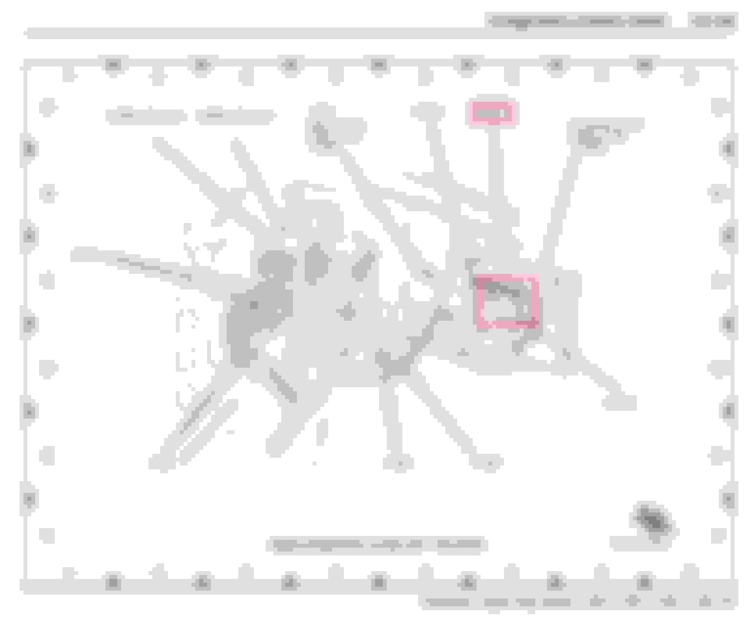
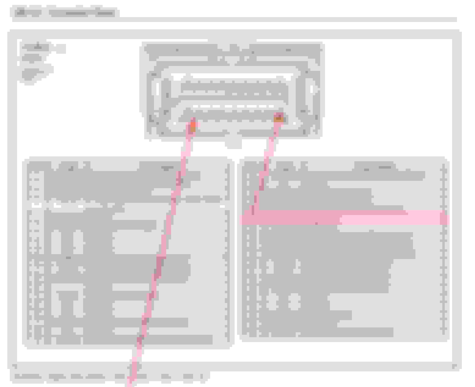
My reading the schematic drawing shows that both wires are going to the PCM. Please walk me through.
One is the ground circuit which is spliced in with the other sensors and controls, pin 44, wire color gy/rd.
The other is the voltage reference and reading, pin 25, wire color lg/rd.
What color wire Mike used for the lay-over, god only knows.
Rezvani's Latest Post-Apocalyptic Monster Is a Ford F-150 Raptor Underneath
Slideshow: Called the Fortress, the 850-horsepower pickup combines Raptor underpinnings with military-inspired features, survival equipment, and a starting price of $285,000.