When you click on links to various merchants on this site and make a purchase, this can result in this site earning a commission. Affiliate programs and affiliations include, but are not limited to, the eBay Partner Network.
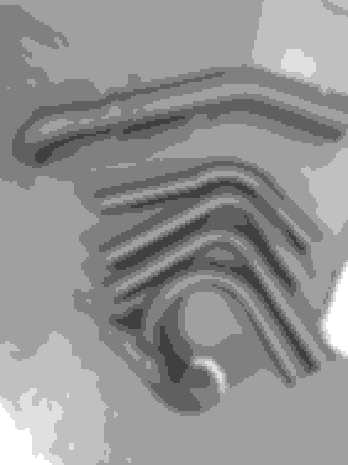
Cold side pipes are back from powder coat and the bottom end and heads are ready for assembly!
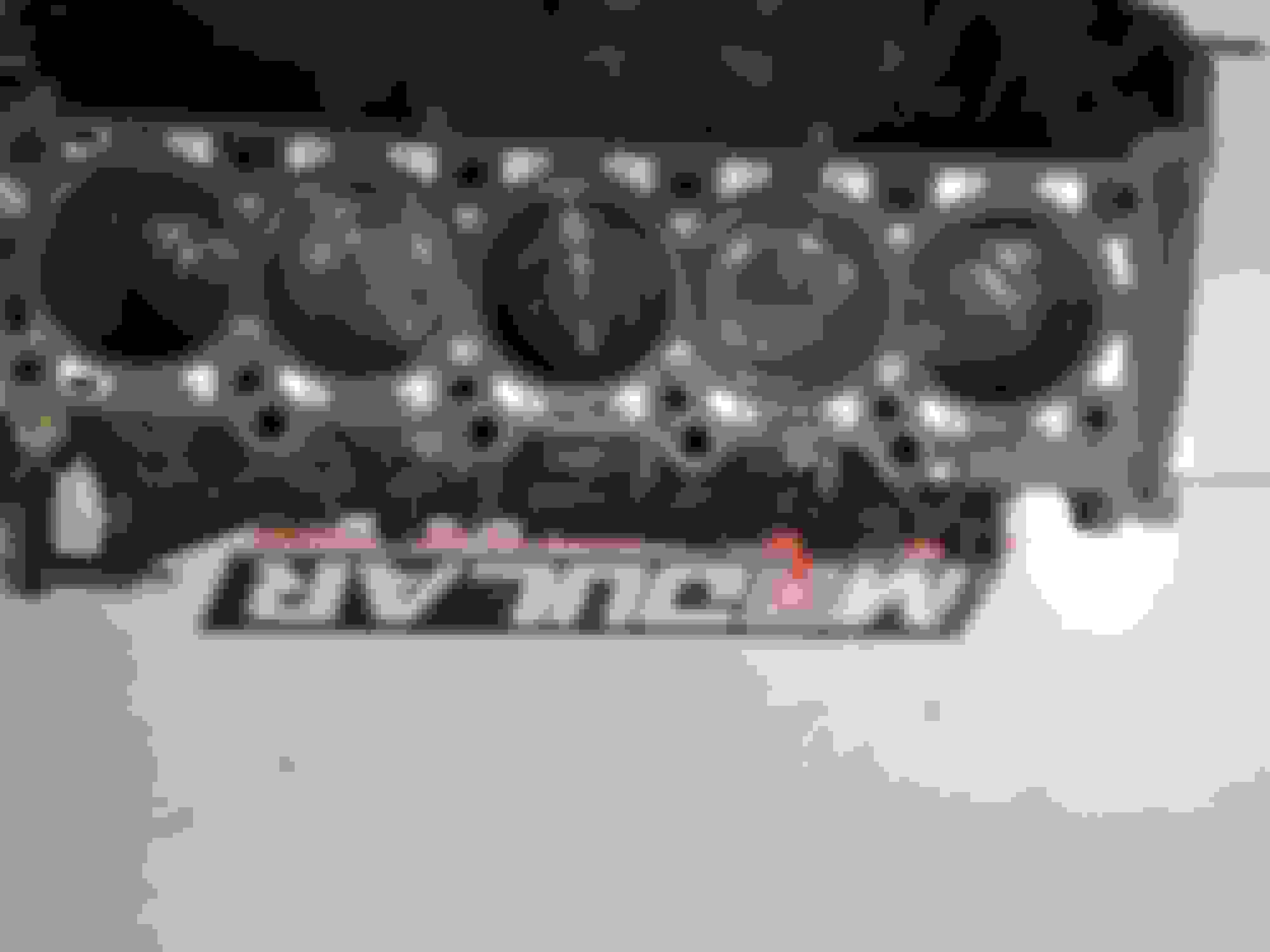
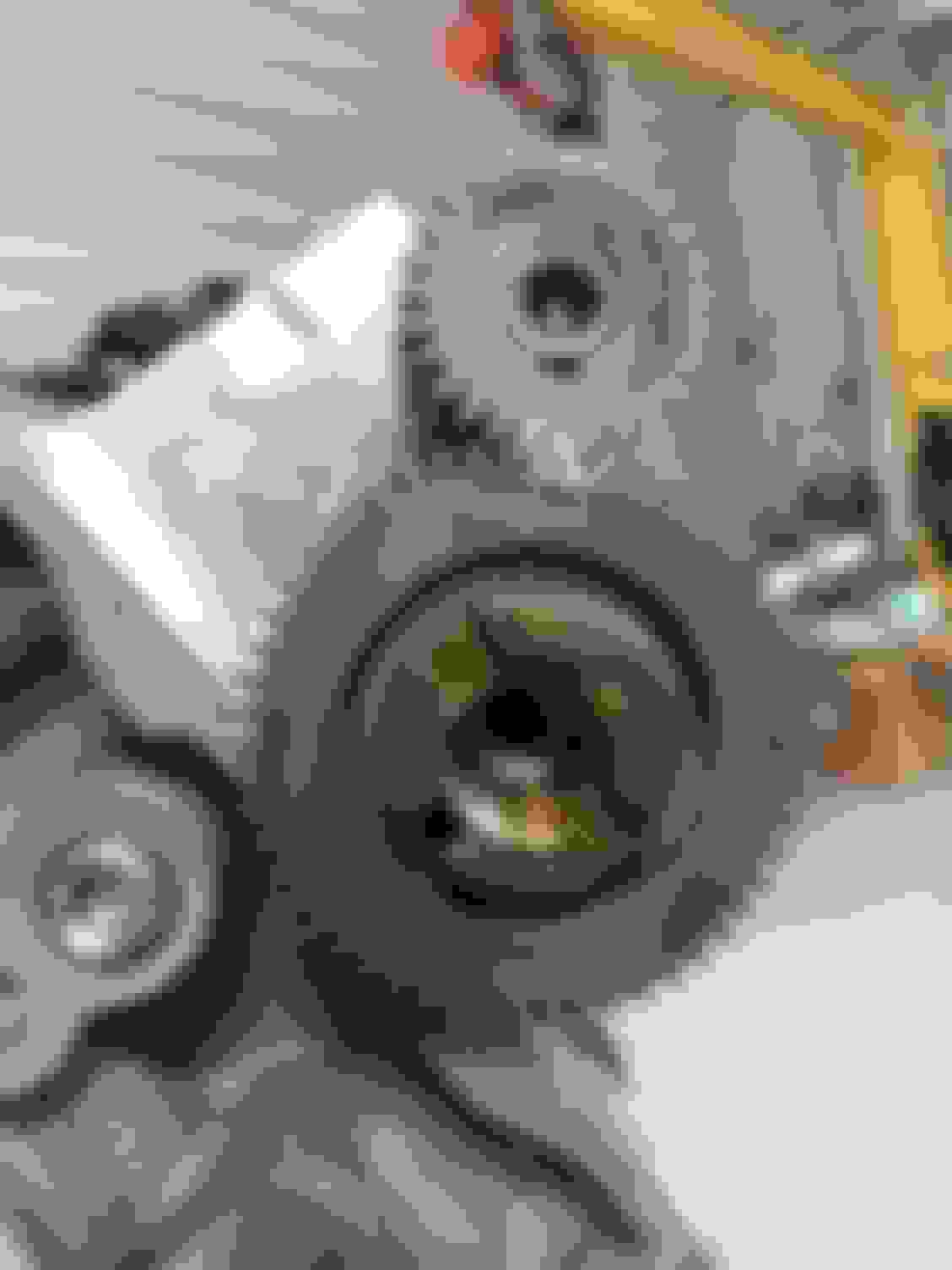
Here you can see the offset and get an idea of how the crank appears weaker due to the overall smaller size of the pin thickness. Another shot of the split pin crank after we balanced it .I kept the rotating assembly light enough to only be off 20 grams. Installing mahle pistons on the Shelby rods.I use Manly pistons almost exclusively in the shop for big hp builds, but for this build we chose to use the mahle due to thier weight and small ring package in a shelf piston. Setting ring end gap prior to piston installation. Installing the pistons/rods
I am intrested in the new weight of rotating assembly......rods, pistons, and how the blance shaft is affected. Or how the rotating assembly is affected by a blance shaft that is weighed for cracked powered metal rods and hyper pistons.
So are these turbos in a compound configuration? What kind of boost pressures> I can't imagine the stress the internals will take
Negative, a compound setup is one turbo feeding the other. This is a traditional twin turbo setup, where each bank of the engine feeds one turbo, and both turbos feed the intercooler............... Plan is to run 14 PSI.
Originally Posted by rock2610d
I am intrested in the new weight of rotating assembly......rods, pistons, and how the blance shaft is affected. Or how the rotating assembly is affected by a blance shaft that is weighed for cracked powered metal rods and hyper pistons.
Do you have any views on this?
I think the balance shaft is more weighted to quell vibrations based on the degree of the engine cylinders, not neccesarly the bob weight.............At any rate if the rotating assembly is balanced and is internaly balance not external like all modular fords, i dont see it being an issue.
The new assembly i used isnt really that much heavier in grand scheme of things. I used sintered forge rods, which arent much different than the powdered rods, about 40 Grams heavier. The pistons were practically a wash, the major weight difference was the pin. The better pins to hold up were about 60 grams heavier per.............. I am just fine with the additional weight, especially with this low rpm motor. I dont see it being a problem.
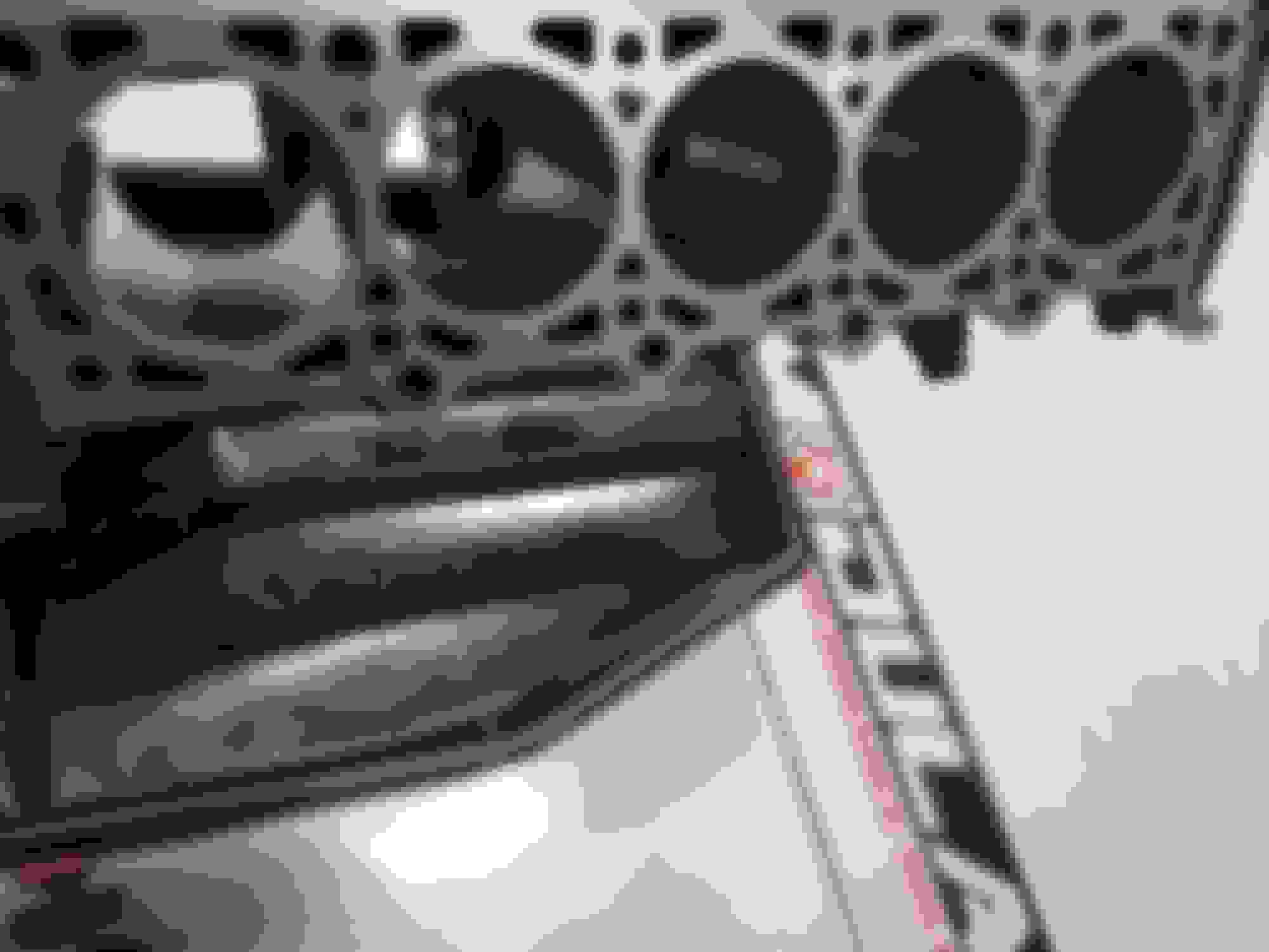
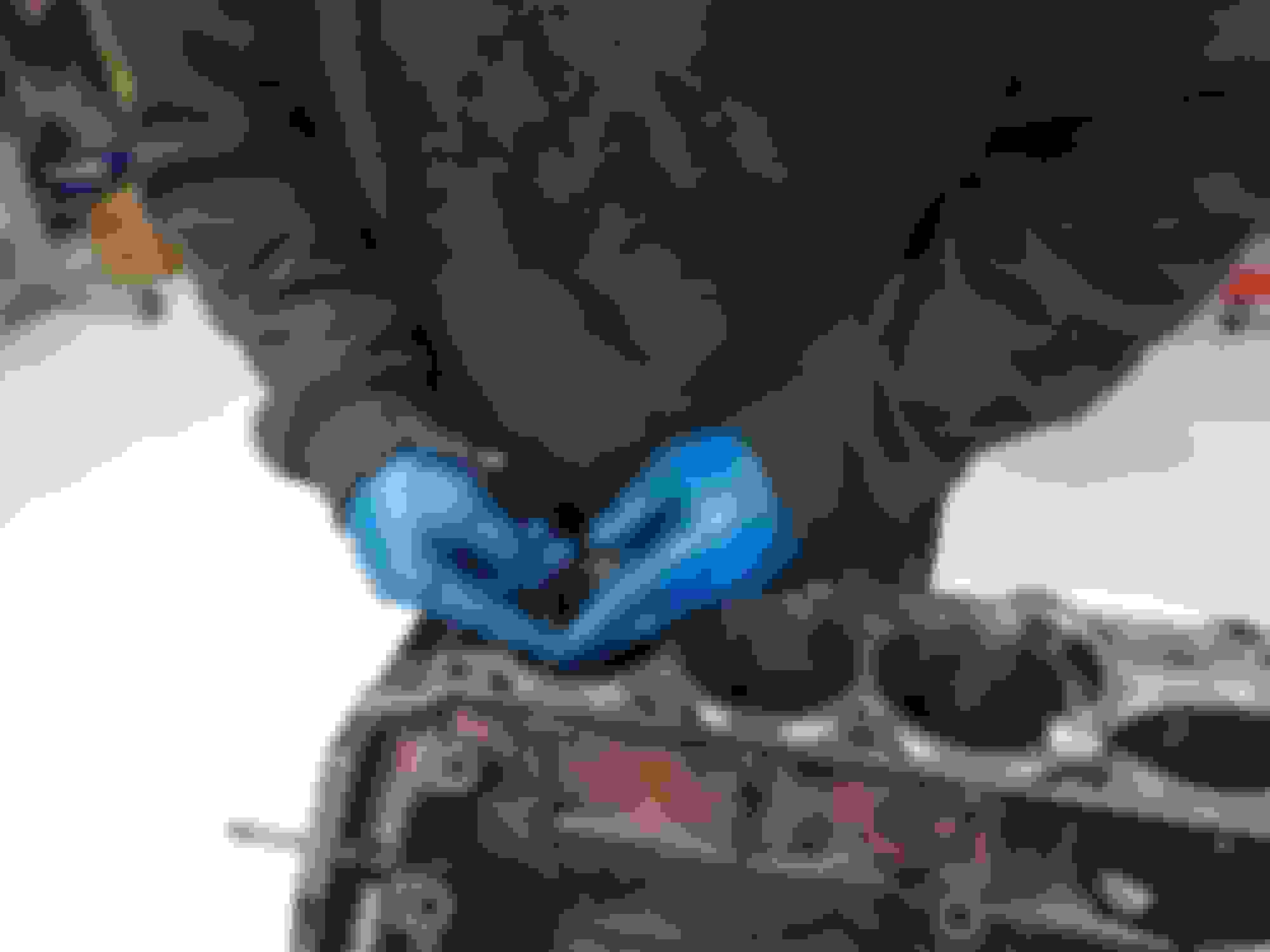
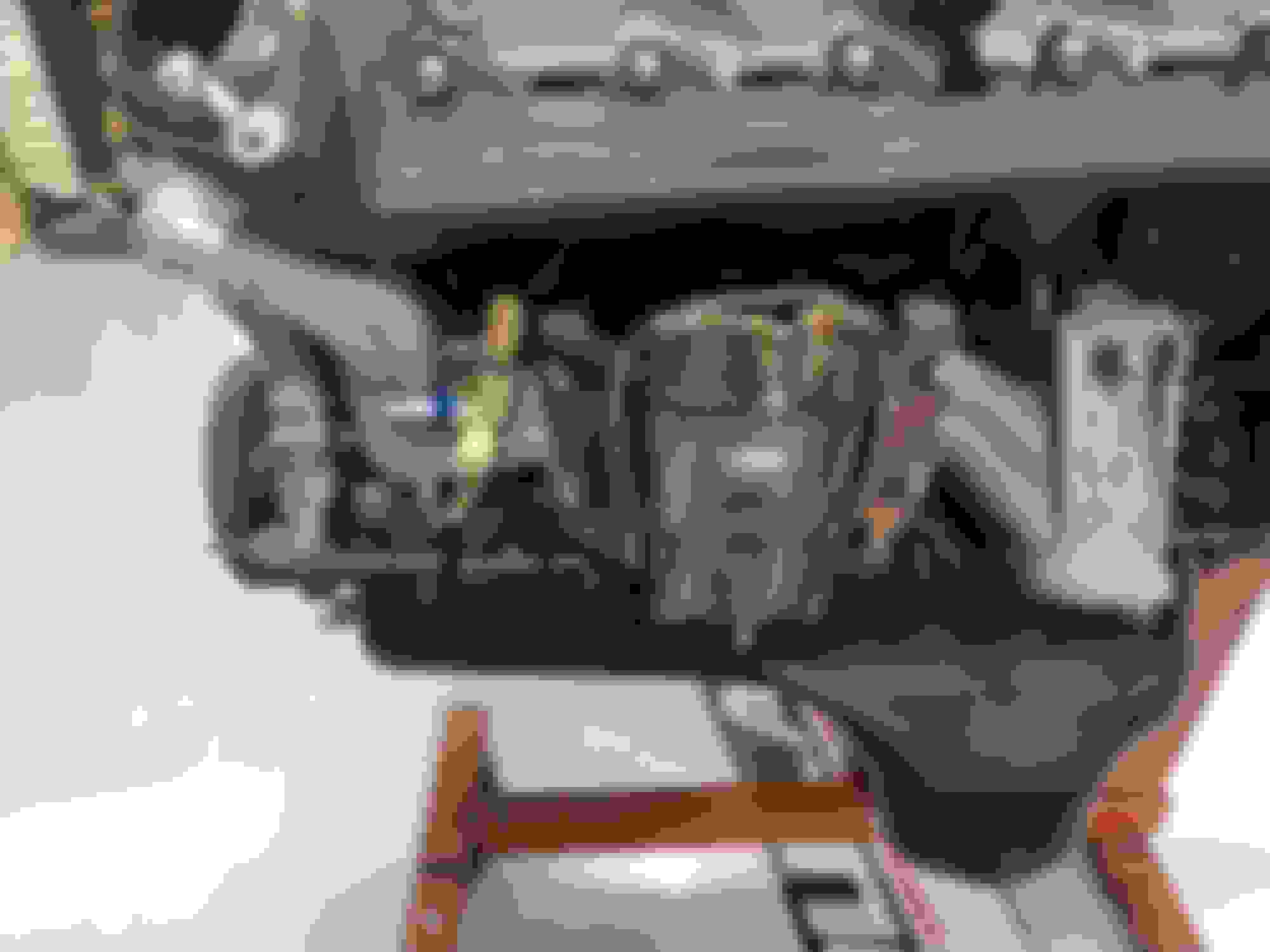
Time to go back in! Heads ready to install after valve job, some bowl work, a deck and some pac springs to handle the boost! Here you can see the small modifications I made on the Chambers. We used a complete Mahle gasket kit for this motor and I was pretty happy with it. Nice gaskets for head and exhaust as well. Balance shaft timing Here you can see how I split my oil feeds up for each turbo and plumbed in the stock sending unit. The driver side turbo drain is welded in the pan under the oil cooler adapter and the pass side drain is under the damper on the front of the pan. Finally! Forged 6.8 ready for a home!
How dI'd you deal with boost pressure to vacuum system and brake booster?
Does fpr "see" boost ?
How did you address boost pressure to drivers side valve cover via the breather hose?
Where did you tap vacuum / boost to run wastegated? I have noticed a 3 to 4 psi difference in boost between upper intake and the runners just before the valves in intake manifold. Probably due to restriction of upper plenum to lower intake connection.
What is the size and manufacture of the turbos?
Inducer and exducer sizes, and turbine AR? Visually the turbine housing looks rather large to run the smaller inducer. Looks like it will take some rpm to push up boost.
It's really a cool thing to see the other performance side of an Excursion (gassers). There are a ton of diesel Excursions out there, mine included, but yours stands out! Nice job and thanks for a great thread!!!
Pictures like this (Keep 'em coming!) make me miss my younger/simpler days when I'd take apart and rebuild an engine.....
I do have to wonder about your attire though. That's too much clothing to have to wear indoors!
Yeah with steel building and a few cold days and doors open and closed the heat can't keep up.
Originally Posted by rock2610d
Nice!
Where did you put the BOV, and MAF. BoV and maf are in intake pipe, Maf is near valve cover but on bottom side so it's not an eye sore, bov is on ds/ intake pipe as well, coming out intercooler, look at pics you can see it.
How dI'd you deal with boost pressure to vacuum system and brake booster?
Brake booster has a check valve, for the other stuff I used a check valve off a lighting/cobra, VW Jetta stuff is available on eBay reasonable as well .
Does fpr "see" boost ? Absolutely, for 1:1 rise
How did you address boost pressure to drivers side valve cover via the breather hose? I **** can all that. I have both valve covers going to a puke tank and then I have one of the turbos pulling a bit of vacuum on the puke tank(filtered of course)
Where did you tap vacuum / boost to run wastegated? I have noticed a 3 to 4 psi difference in boost between upper intake and the runners just before the valves in intake manifold. Probably due to restriction of upper plenum to lower intake connection.
I referenced gates from the compressor, so I tapped the compressor housing for a fitting and sent that directly to gates, you want gates to see boost only, the bov needs boost and vacuum to operate properly.
What is the size and manufacture of the turbos?
Inducer and exducer sizes, and turbine AR? Visually the turbine housing looks rather large to run the smaller inducer. Looks like it will take some rpm to push up boost.
Probably just the photo angle or perspective, these are very small turbos for a V10 (Garrett 3071s), have the small housings, I'll have to check the atp website to see what size they are. I had em laying around from a previous deal, they are billet wheel ball bearing, water cooled, very pricey as well. If I was buying it would be small precision turbos or some Borg Warner s366s fwiw .
I'm seeing boost as low as 1400 rpm. It's on the spring at 1900.
Originally Posted by Downsized2X
It's really a cool thing to see the other performance side of an Excursion (gassers). There are a ton of diesel Excursions out there, mine included, but yours stands out! Nice job and thanks for a great thread!!!
Thanks! It was a fun build. Still quite a bit to do to finalize it .

 11-09-2018, 12:10 PM