When you click on links to various merchants on this site and make a purchase, this can result in this site earning a commission. Affiliate programs and affiliations include, but are not limited to, the eBay Partner Network.
This is a work in progress, but tonight I got a digital display to work with the 92 to 96 speedometers speed output signal.
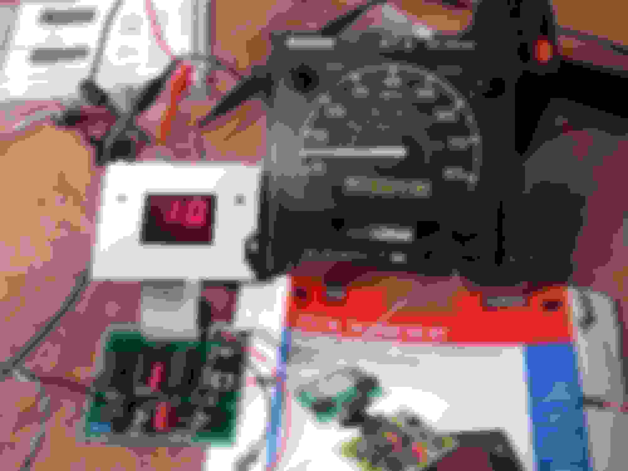
At 10MPH
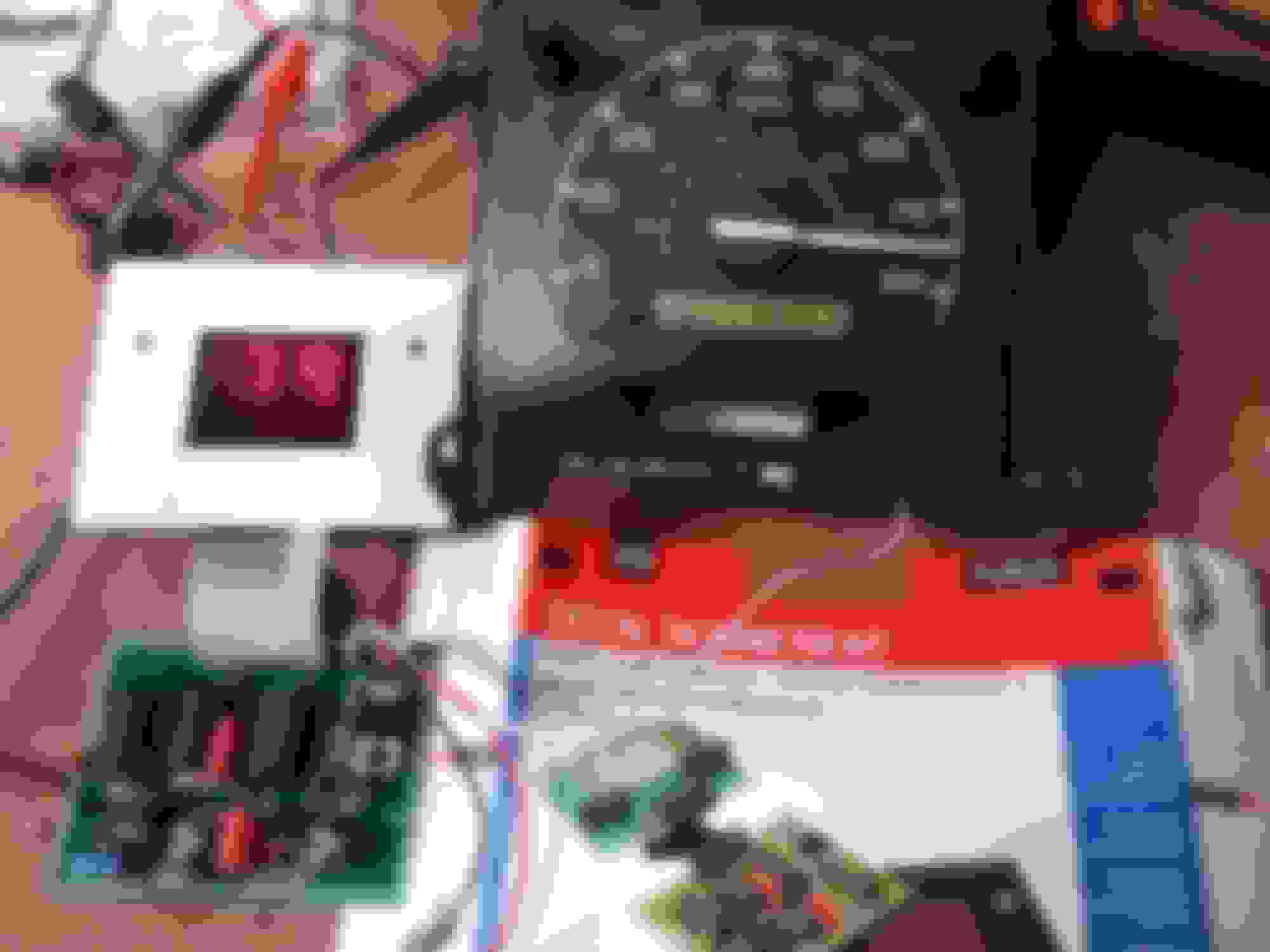
At 45 MPH
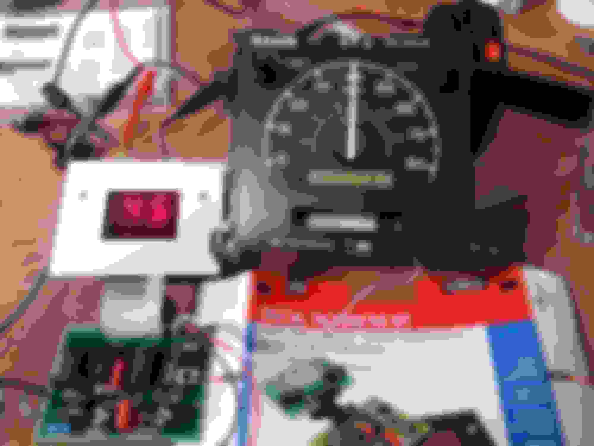
At 80 MPH
The display kit I used is in the photos: Velleman K2625 digital tachometer display.
I put it together with no mods and tuned it right in by feeding a PSOM a simulated VSS to get 45mph on the speedometer's display.Then adjusted the digital display to 45MPH. I was really surprise as the above photos show its almost 1mph of the analog display!
Below is a good PSOM speed signal output, that goes to the ECU and speed control AND the new digital display
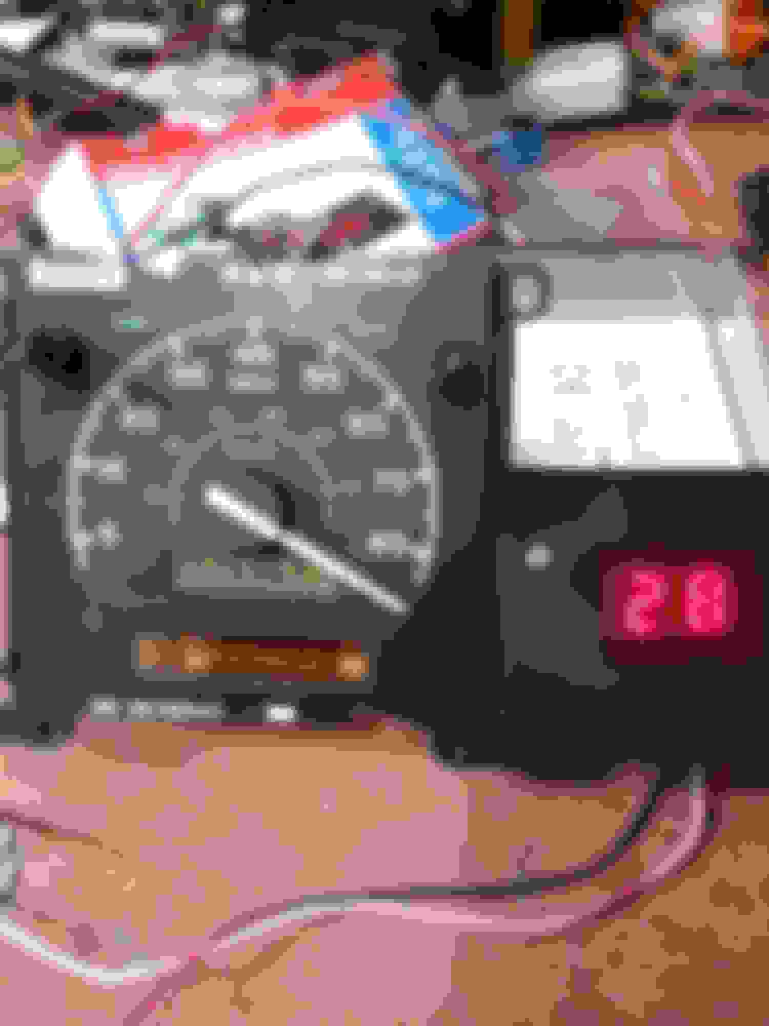
Out of curiosity I cranked up the VSS signal to see how fast these speedometers are capable to going.
This one was stable to 128mph on the speed output. Now just need a 3 digit display to show the 100's!!
This one was stable to 143MPH!!! Now to look for a 3 digit display..... I pulled(and lost) the stop pin to see what the needle does. It only goes to that point and will not go past it...
As this is a work in progress, things will change, but for the most part it worked right off the bat! Some mods will be done as I found the voltage regulator IC in the display kit runs hot, a heat sink should fix that. Also the kit is kinda bouncy between numbers(45, 46, 45, 46 ect...) I suspect its the 50% duty cycle of the speedometer signal causing it. The kit was originally a engine tachometer and that signal is usually less than 10% duty cycle with no negative voltage levels. The PSOM speed signal is a quasi AC output. More testing will occur.
I installed the digital speedo in my 95 E350 today. I verified with a few of those radar speed signs around town and the display was spot on!
In bright daylight it is viewable, not sure how bright at night it will be. There is a way to dim the display down built in it.
Originally Posted by Scndsin
That's a really cool tinkering project just searching for an application. Thanks for posting.
Sure looks like the needle goes past where the stop pin was just fine in the photo.
Yep, a digital dash board like the late 80's T-Bird and Chrysler K-cars had.
The speedo meter movement will go beyond the stop post, but it cannot go beyond that point electronically driven. Its just the way the meter is designed. The stop post is there to keep the needle from pegging over and jamming up.
Day time it is visible unless direct sun light is on it(same issue with the VFD gauges). Night time is not too bright and looks good.
The input of the digital display should be redesigned so it will see a true AC waveform instead of a 0v to 12V pulse of original design. I think this is the cause of the display bouncing between two numbers (54/ 55 /54/55 ... ect). But for the most part it is a stable display!
Still 2 digit only? Got a pic of where you put it?
The kit is only a 2 digit display. I have not found any 3 digit kits, will have to design one up......
I never permanently mounted it yet, just laying on the cluster face for now.
I am going to make up a digital dash cluster eventually, just ordered some kits that use the ICL7107 3.5 digit LED drive IC. I get the kits as they have pre made PCB's which makes this easy to build and modify.
I read through some of your threads about reprogramming psom eeproms. I see it was a few years ago and was wondering if you have made any more progress disseminating the chip data. I'm building a 76 F250 Camper Special with a 460 and c6. I swapped in a sterling 10.25 out of a 93 F350. I have been able to wire in a psom and have it work but still trying to get calibration correct. I'm wanting to possibly incorporate the psom into my stock speedometer housing but the ranges differ, 85 mph vs 100 mph. I read where you found a scale calibration in the software. Could that be used to alter and correct the needle sweep to read correctly on a 100 mph face?. Would you be willing to share how you reset the calibration lock out counter?
I have not messed with the PSOM programming since then. I have to dig around on which data segment was for the lock out.
As these PSOMS are coming to "End of Life" and are failing for other issues, I since started to figure out on using a Arduino and LCD/LED displays to recreate a instrument cluster. Been kicking around the though of using a Arduino to drive the speedometer drive motor and using a OLED display in place of those failing LCD displays in the PSOM speedometer to keep a factory look. But too many projects ahead so thats on back burner for now...
@Eddiec1564 , this is a totally useless mod to me. But, fricken-A, it is cool as hello jello, and I'm gonna follow this, and try and find a reason to do it! LOL
I'm collecting parts for ZF 5 speed swap and the transmission I have came from a 93 so no speedometer, hence the psom experiment. I know gps speedometer driver units are available but expensive.
This Hennessey Takes the Expedition Tremor's Off-Roading Capability to the Next Level
Slideshow: The VelociRaptor Expedition gains a lift, upgraded suspension, Brembo brakes, and trail-ready equipment while retaining the stock 440-horsepower EcoBoost V6.
Rezvani's Latest Post-Apocalyptic Monster Is a Ford F-150 Raptor Underneath
Slideshow: Called the Fortress, the 850-horsepower pickup combines Raptor underpinnings with military-inspired features, survival equipment, and a starting price of $285,000.