When you click on links to various merchants on this site and make a purchase, this can result in this site earning a commission. Affiliate programs and affiliations include, but are not limited to, the eBay Partner Network.
Ok i believe I figured out two of them. But the last one with the fuseable link that goes back to the cab I have no idea where it goes.
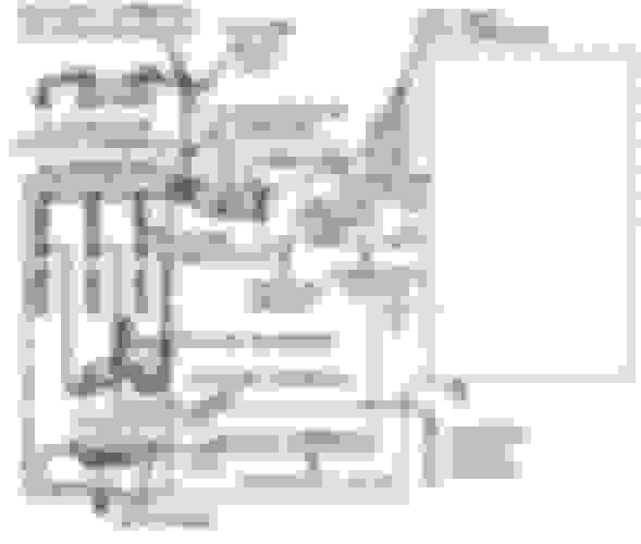
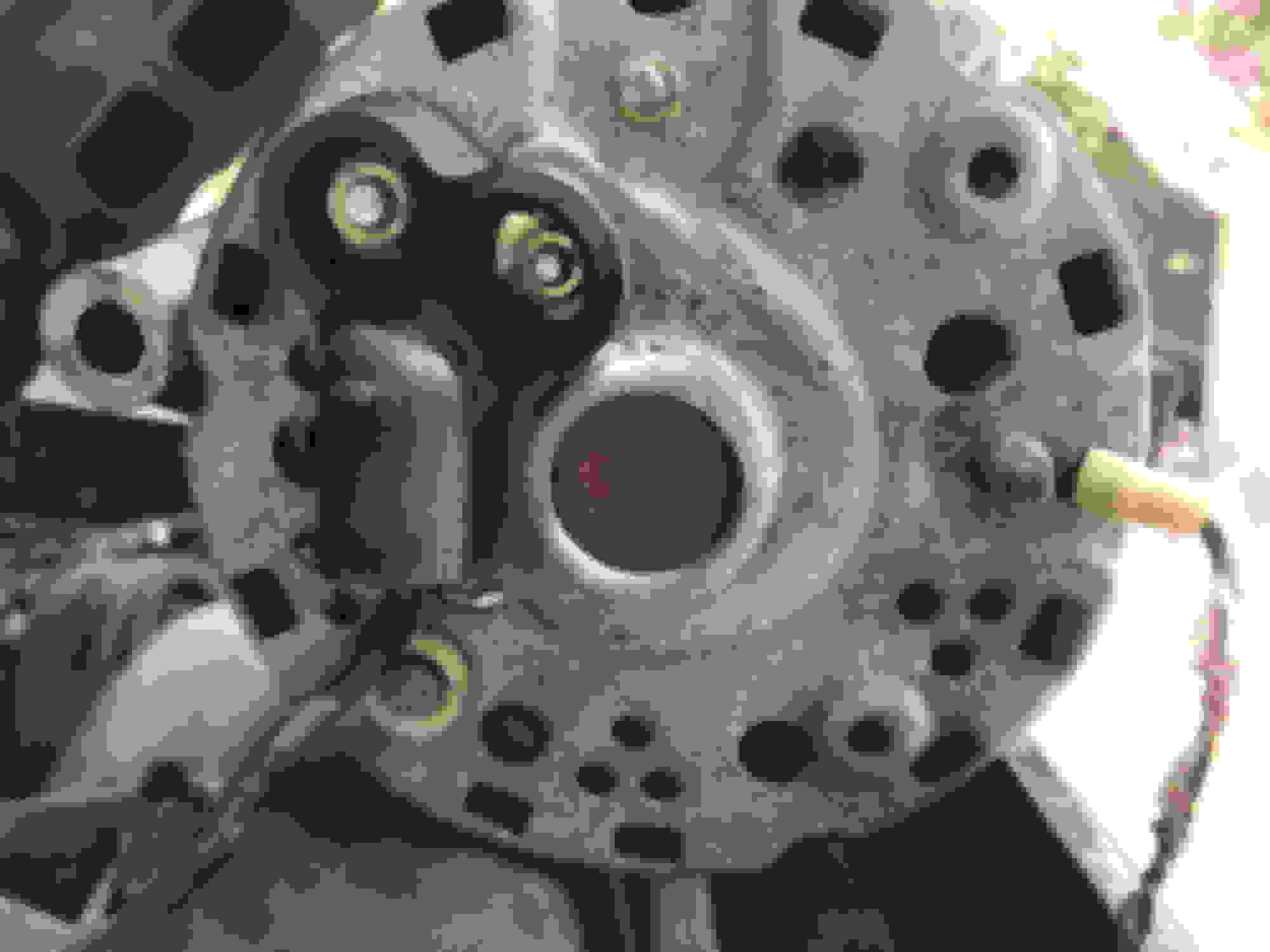
I took a short video.
The fusible link wire (blk-yel) connects to the hot (+) side of the starter solenoid. Tripple ck EVERYTHING BEFORE you turn the key.
Very nice thank you . So if you saw the video I kind of screwed up. I should have said in it that all three wires were taped up and together so they all came to the alternator. But in the video I had already pulled off all the brittle tape.
You say it should go to the starter solenoid and I can see that in the picture.
but the way it was all taped up there was no way that fused link was going to come all the way back to the starter solenoid if it was next to the alternator. Could this be plugged into the I on the back of the alternator?
Regulator
S: needs 12 volts with the key in RUN.
A: needs 12 volts at all times.
F: goes directly to FLD stud of the alternator.
Alternator
Large stud (BATT, B+ sometimes A): goes to the battery side of the starter solenoid through a fusible link, also branches out to the 'A' terminal of the regulator to satisfy its 12 volts at all times requirement.
STA: goes to the electric-assist choke ONLY. NO connection to the regulator.
FLD: goes directly to the 'F' input of the regulator.
Also, it's very common (and recommended) to run a small ground wire from one of the regulator mounting bolts to the GND stud on the back of the alternator, if available. Very little current flows through here; it's just to help close the regulator sense loop.
That purple wire looped back on itself tells me you have an ammeter (gauges and not idiot lights), yes? That's the shunt wire for it.
And in case you want to replace the alternator wiring harness, that's the one that goes from the alternator to the regulator.
Harness, alternator wiring
Fits 78 F100-350 w/amp and oil press gauges. All engines and 70 amp Ford alternator
D8TZ-14305-B
Green Sales, Cincinnati, OH has 40 (800) 543-4959
And in case you want to replace the alternator wiring harness, that's the one that goes from the alternator to the regulator.
Harness, alternator wiring
Fits 78 F100-350 w/amp and oil press gauges. All engines and 70 amp Ford alternator
D8TZ-14305-B
Green Sales, Cincinnati, OH has 40 (800) 543-4959
Yessuh, your diagrams all look pretty good....with a coupla three "clarifications."
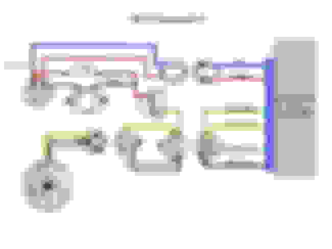
Your First diagram, top left:
There's an 'I' terminal that's not used. The 'S' terminal on the voltage regulator is for switched 12 VDC...only hot in RUN, from the ignition switch. From the ALT 'S' terminal it goes to the automatic choke, that's it. Not used any other time unless someone wants to run a switched 12 volt source....lots of wiring there. Pretty much what you have....but you knew that.
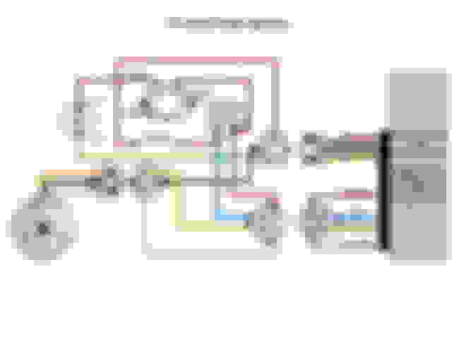
Your Middle diagram:
The START/BYPASS and BALLAST RESISTOR circuit.....a bit confusing as to the "12v at RUN" (ignition switch picture) and "RED GREEN - HOT while on RUN 12v." To clarify - yes, 12 VDC is supplied from the ICM while in RUN from the truck. Goes through the ballast resistor in RUN and reduced to 6 -9 VDC.
In START (at the start bypass red wire at ignition switch in yer picture), there is not 6v constant.....there is 12VDC there ONLY in START.
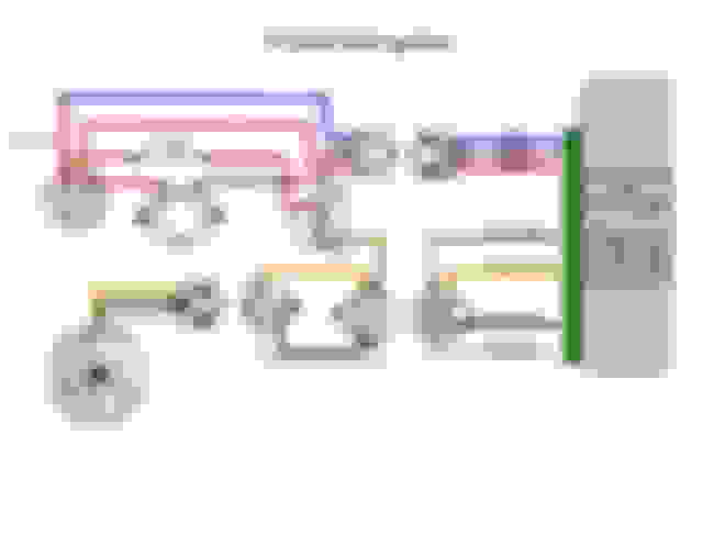
The last diagram:....Again the automatic choke (if used) only gets power from the S terminal on the ALT.
I know you knew all this....and I appreciate your vote of confidence in me
My answers might be considered "nit pickin' but, we all try to be thorough, yes?
FB you have WAY to much confidence in my capabilities. lol I got those diagrams off FTE and am not a wiring guy AT ALL. I appreciate your much more educated eye and opinion on them. I will repost the pics (with your input) in the "and then some" thread. https://www.ford-trucks.com/forums/1...l#post17724184
Ahhh, Rich..don't sell yerself short....as in I know you're at least 5' 10".........
Anyway, in my haste to answer you before my session "timed out," I didn't mention that the middle picture you posted was from a '78 on up, and have only TWO wires in and out. You know the color coded wires coming from the ICM are red and white and going into the engine side of the connection they're white and red....180* out. Why did Ford do this? Arrrr, to confuse us more I 'spose....
And the color codes and number of wires change with the grommet (Model Year) color.
By no means are my pictures cut in stone....just a pretty good summation of the stock setup.
I'm sure Mr Bill will be along to clarify all this.....He likes you....
Thanks again for your confidence in me, my friend...
Thank you all for the help !! Had to rewire stuff thanks for the blue prints to follow.
Got it all worked out.
Got to fire up the the truck tonight for the first time since I rebuilt the motor last yr.
Was awesome to hear it run.
But I was scared crap less at first. I had just got done rewiring and went to start it and nothing . NO engine crank. Found the starter relay was bad. replaced it and fired right up.
Again thanks for all your help.
Yet another bad one for the list.
But at least this time it looked like an older unit in the video. They do eventually die out. Just that the new ones seem to die very quickly indeed.
So more than ever it pays to have a spare (a known good one!). And more than ever we need to remember that even though we replaced a part, that does not mean we can rule it out if we have another related problem.
Always suspect the new parts too.
Congrats on getting it up and running!
1TonBasecamp your right on about the parts being bad right out of the box. amazing how many new ones are bad. Batteries , alternators , starter relays and the list goes on.
Back in the day when I had duraspark I always carried one extra of those and starter relay plus a coil.
Piggy backing off an outstanding thread. Hopefully all of you are still available for my charging problems. Just bought a 69 F250 with a 390. Previous owner stated it had a charging / alternator problem. I popped the alt out and immediately noticed a wiring issue. It�s a 3 wire setup but the yellow wire has clearly seen some high current. The stud it�s attached to isn�t labeled. It�s also lacking a ground. This has me worried. Alt tested good. Now I�m just trying to verify it�s been wired correctly. I have fusable link wire and ground wire I�m running today. Any help in clarifying the current wiring chaos and what it �should� be would be great. Thanks.

 01-12-2018, 04:51 PM


 thank you Ill give this a try in the morning