300 RV Motor - Project Bulletproof
#16
 11-16-2017, 03:41 PM


Join Date: Nov 2008
Posts: 106
Likes: 0
Received 0 Likes
on
0 Posts
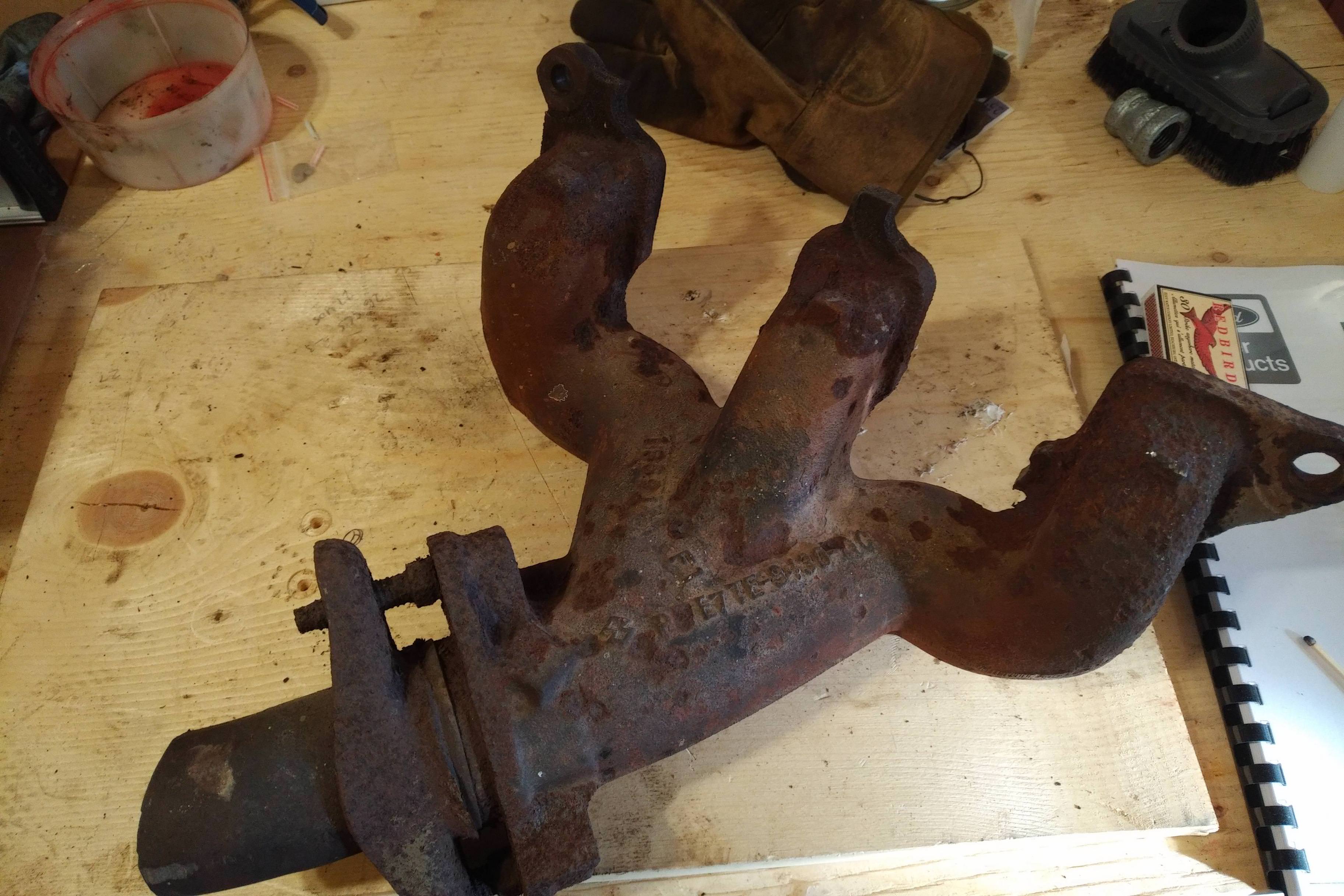
Well this showed up in the mail today. Just need the other half, and then at least the exhaust part is done.
I was doing some more reading, and with regards to my thoughts about bumping the compression, the "Bulletproof" angle is putting an interesting spin on things. Bumping the compression on a motor gives a guy more horsepower it seems, but it's at the expense of wear and tear on the motor.
The theory here is that lower compression will actually increase the lifespan of parts, all other things being equal. So chasing higher compression by shaving heads or swapping pistons, while giving a guy more power and such, arguably makes engine life shorter.
Now I don't know what that equates to when you're comparing an 8:1 compression ratio to say a 9.5:1 ratio, but it did get me thinking. Plus the fact that lower compression motors will run on crappy old gas, makes me think that keeping an 8ish:1 ratio might be the thing to do, given the premise of this project.
Seems counterintuitive though, when usually all the builds I see typically try and increase power wherever possible.
#17
11-16-2017, 08:59 PM


Well this showed up in the mail today. Just need the other half, and then at least the exhaust part is done.
I was doing some more reading, and with regards to my thoughts about bumping the compression, the "Bulletproof" angle is putting an interesting spin on things. Bumping the compression on a motor gives a guy more horsepower it seems, but it's at the expense of wear and tear on the motor.
The theory here is that lower compression will actually increase the lifespan of parts, all other things being equal. So chasing higher compression by shaving heads or swapping pistons, while giving a guy more power and such, arguably makes engine life shorter.
Now I don't know what that equates to when you're comparing an 8:1 compression ratio to say a 9.5:1 ratio, but it did get me thinking. Plus the fact that lower compression motors will run on crappy old gas, makes me think that keeping an 8ish:1 ratio might be the thing to do, given the premise of this project.
Seems counterintuitive though, when usually all the builds I see typically try and increase power wherever possible.
I was doing some more reading, and with regards to my thoughts about bumping the compression, the "Bulletproof" angle is putting an interesting spin on things. Bumping the compression on a motor gives a guy more horsepower it seems, but it's at the expense of wear and tear on the motor.
The theory here is that lower compression will actually increase the lifespan of parts, all other things being equal. So chasing higher compression by shaving heads or swapping pistons, while giving a guy more power and such, arguably makes engine life shorter.
Now I don't know what that equates to when you're comparing an 8:1 compression ratio to say a 9.5:1 ratio, but it did get me thinking. Plus the fact that lower compression motors will run on crappy old gas, makes me think that keeping an 8ish:1 ratio might be the thing to do, given the premise of this project.
Seems counterintuitive though, when usually all the builds I see typically try and increase power wherever possible.
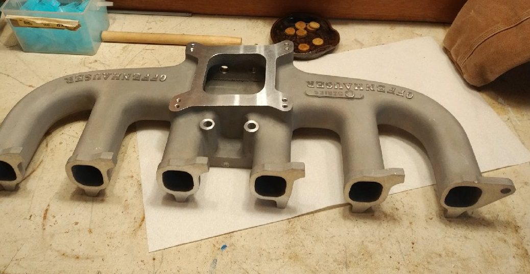
Looks like you could use this:

It's a manifold I ported last march. I don't need it because I'm building headers for all my 240/300 projects. I just ported it to show what kind of improvement could be achieved by porting the EFI manifolds. More info about it here. https://www.ford-trucks.com/forums/n...ply&p=17596454
If you are interested I'd be willing to sell it. But if you did get this then you'd have to port the one you've got.
As far as the compression goes you are talking about 9.0:1-9.2:1 not 15.0:1. A compression ratio in the low 9's is not going to hurt the longevity of the engine. But you can help it even more by taking minimum cuts from the head and block. Just enough to clean up the surfaces. Get the compression bump by either swapping to a 240 head or changing pistons. A 8:1 300 is going to be a dog. Have the machine work done that should be done. And take care of the few weak links that the 300 has ( Head gasket and pistons ) . And beef up the areas you can. Go with ARP rod bolts and either ARP head bolts or studs and ARP rocker studs( if you change out the originals ) .
Can you get the casting # off the bottom front edge of your cylinder head? It should be something like "C8AE" or D2TE. If it has a "A" it's a 240 head. If it's a "T" it's a 300. I looked at your pictures of the combustion chambers. I'm pretty sure your head is a 240 head.
This pic shows a 240 and 300 head. The front head is a 240 and the rear one a carbed 300. You can see the different shape of the combustion chambers.

#18
11-17-2017, 10:00 AM
Join Date: Nov 2008
Posts: 106
Likes: 0
Received 0 Likes
on
0 Posts
Well last night I got a few things done.
First, tried a leak test with the valves. Filled each combustion chamber with some varsol, and waited for leaks. Didn't see anything after leaving things for a few hours, so I suppose that's a positive.
Secondly, decided I would take a look at the bottom end and see how things are looking.
Pro Tip: Remember to drain the oil first before you flip a block over. (Had a brain-fart again and just assumed there wouldn't be any oil in the block. Wrong.) So after being delayed by an unknown oil spill, I popped off a main bearing and a rod bearing just to see how things looked.
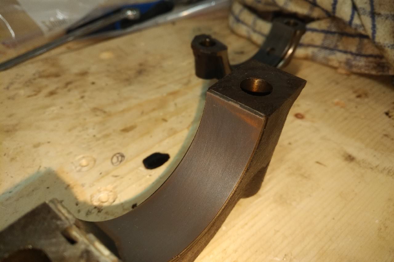
Main bearing:
Rod bearing:
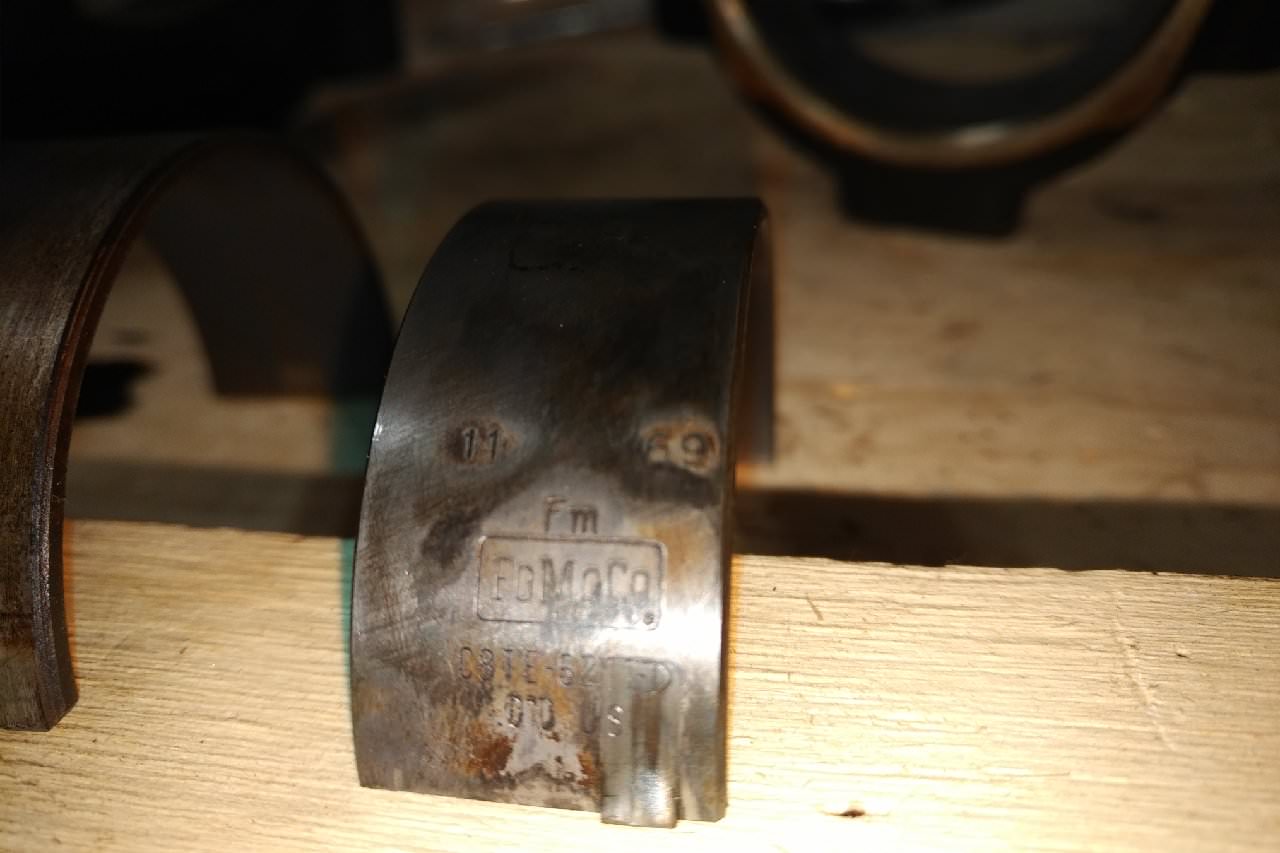
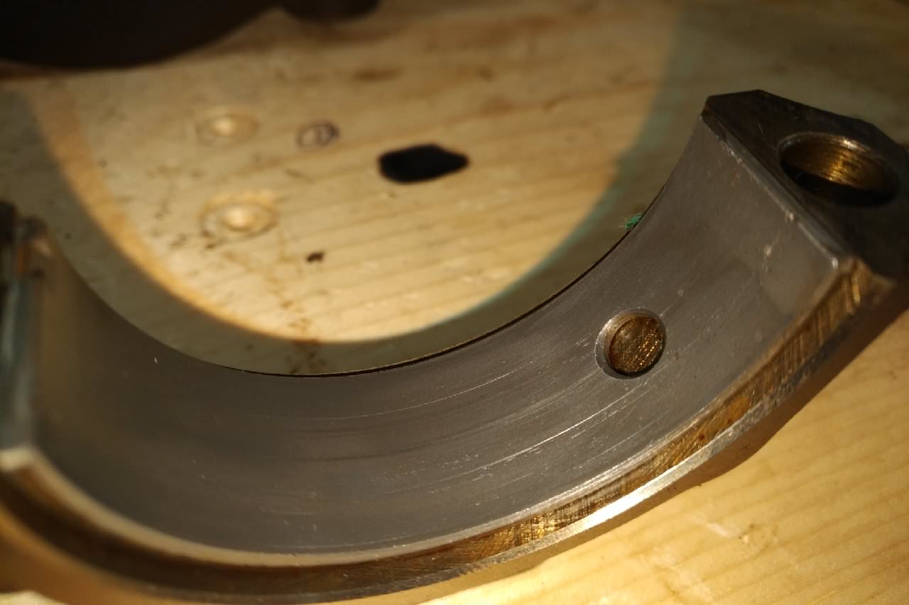
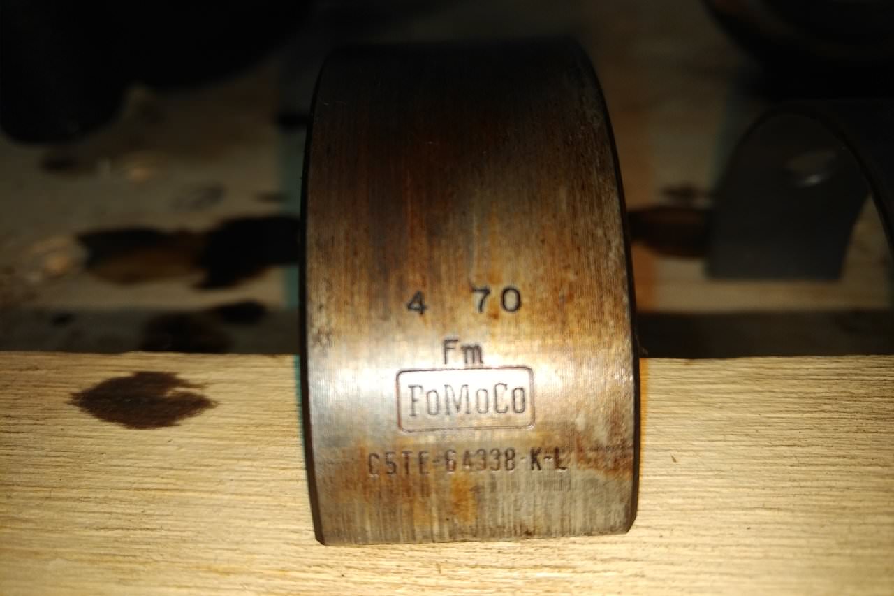
I think the bearings look OK (a bit of wear, but nothing super bad) but I'm no expert at these things. The one thing that does jump out at me though is I swear that rod bearing is stamped ".010". Here's another photo
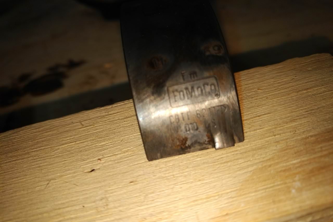
What's unusual to me about this is the bearings look like OEM bearings from ford. On top of that, they are dated "11 69", which to me says November of 1969. (The mains say 4 70, Apr 1970?). The guy I bought the motor from said it was out of a 1970 Winnebago, so the bearing dates seem to validate that.
However, why would Ford put .010 undersize bearings into an otherwise factory motor? Has anyone seen this before?
Anyway, Plastigauge showed up today, so probably this weekend I'm going to check all the bearing surfaces and hopefully everything is still in spec.
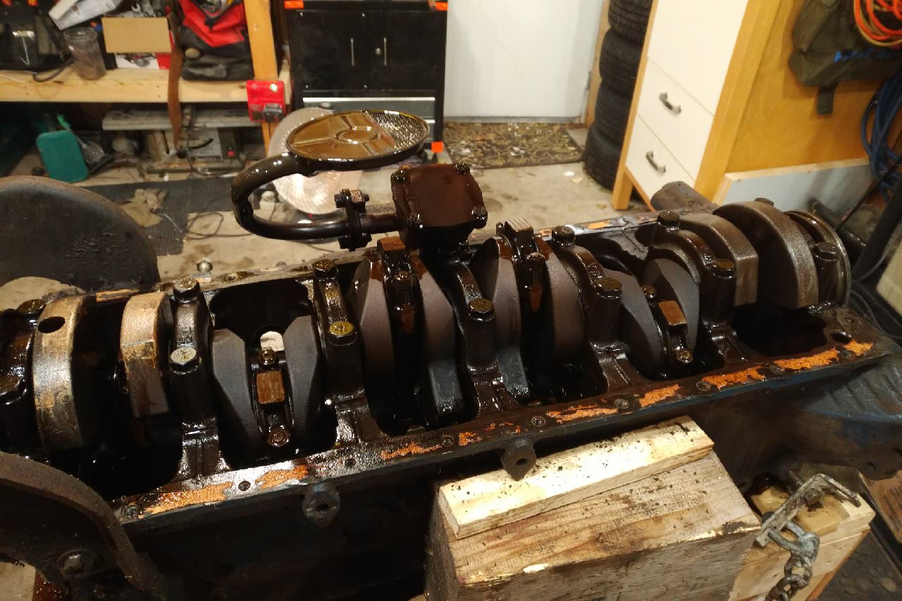
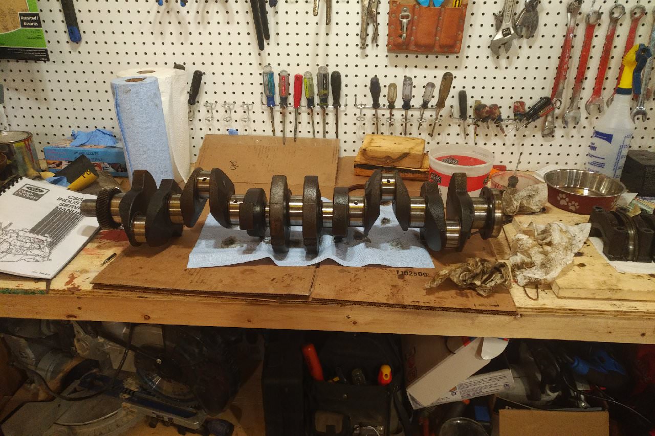
Edit: Forgot to add a couple pictures of the crank. Looks like it's cast?
First, tried a leak test with the valves. Filled each combustion chamber with some varsol, and waited for leaks. Didn't see anything after leaving things for a few hours, so I suppose that's a positive.
Secondly, decided I would take a look at the bottom end and see how things are looking.
Pro Tip: Remember to drain the oil first before you flip a block over. (Had a brain-fart again and just assumed there wouldn't be any oil in the block. Wrong.) So after being delayed by an unknown oil spill, I popped off a main bearing and a rod bearing just to see how things looked.
Main bearing:
Rod bearing:
I think the bearings look OK (a bit of wear, but nothing super bad) but I'm no expert at these things. The one thing that does jump out at me though is I swear that rod bearing is stamped ".010". Here's another photo
What's unusual to me about this is the bearings look like OEM bearings from ford. On top of that, they are dated "11 69", which to me says November of 1969. (The mains say 4 70, Apr 1970?). The guy I bought the motor from said it was out of a 1970 Winnebago, so the bearing dates seem to validate that.
However, why would Ford put .010 undersize bearings into an otherwise factory motor? Has anyone seen this before?
Anyway, Plastigauge showed up today, so probably this weekend I'm going to check all the bearing surfaces and hopefully everything is still in spec.
Edit: Forgot to add a couple pictures of the crank. Looks like it's cast?
#19
11-17-2017, 10:16 AM
Join Date: Nov 2008
Posts: 106
Likes: 0
Received 0 Likes
on
0 Posts
Fordman,
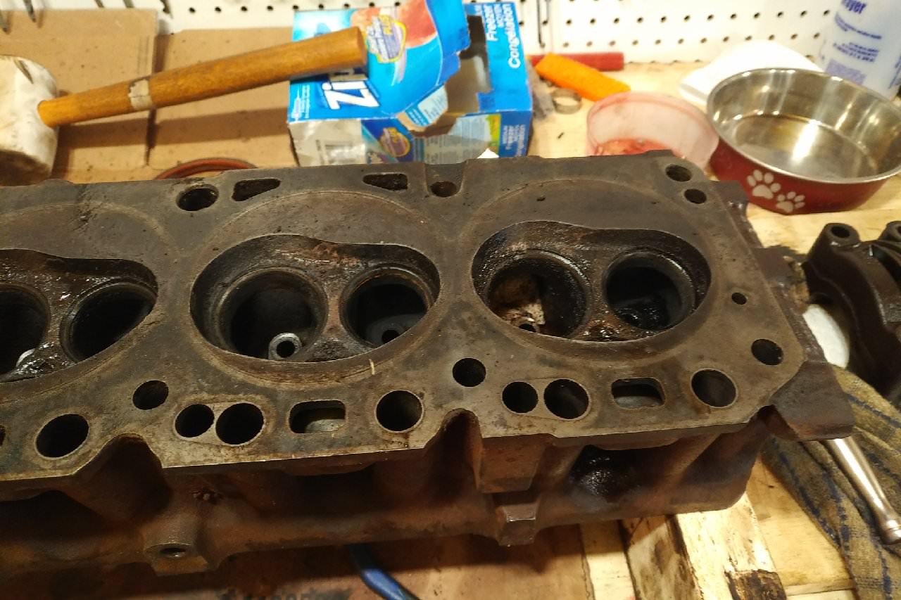
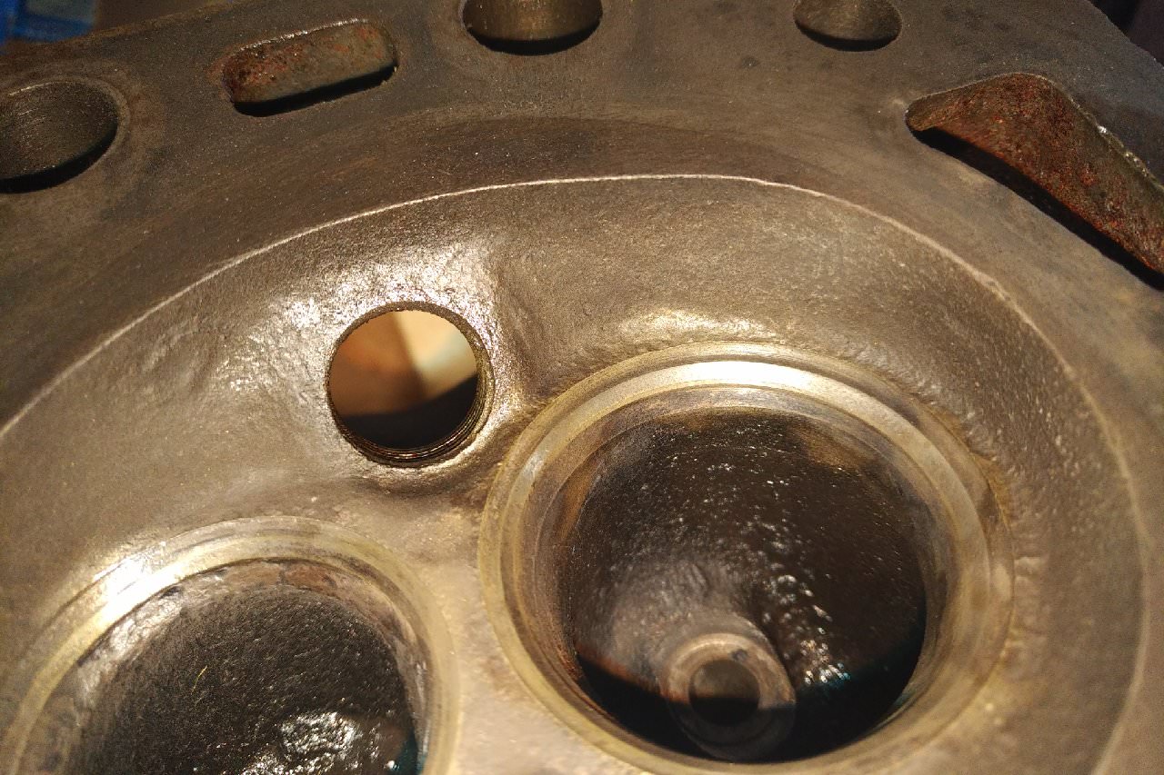
Well if 9:1 vs 8:1 doesn't "hurt" anything, then it makes sense to go for 9:1 then. And if a 240 head does that, and I possibly even happen to have one sitting in my garage, then even better. I will check the casting number later today, but for now here are the combustion chambers (not sure if I already posted this)
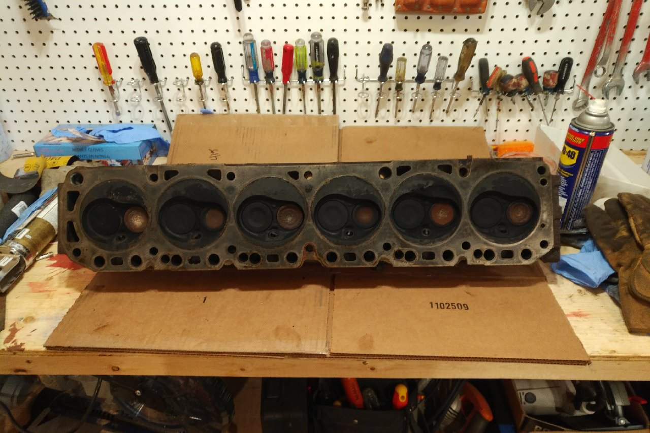
They look "kidney" shaped to me, but I suppose the casting number will be what's needed.
Well if 9:1 vs 8:1 doesn't "hurt" anything, then it makes sense to go for 9:1 then. And if a 240 head does that, and I possibly even happen to have one sitting in my garage, then even better. I will check the casting number later today, but for now here are the combustion chambers (not sure if I already posted this)
They look "kidney" shaped to me, but I suppose the casting number will be what's needed.
#20
11-17-2017, 11:50 AM

Crankshaft
Does look like .010 rod bearings -if I remember right rod journal should mike 2.123 for standard. I worked for Ford for 40 years in a dealership and I have seen this a few times. This would happen mostly on service replacement parts. Example like a replacement short block assembly
#21
11-17-2017, 05:08 PM
That's a cast crank. Could you find the Casting #'s on the crank. I think you might want to confirm that it's a 300 and not a 240. The piston dish design looks like a 300 to me. But you should confirm to be safe. Being a cast crank I think it'll be Something like "1N", "1NA", "1NABC", "2N", "2NA", "2NABC" for the 300 crank. If it's a 240 crank it'll be "1L", "1LA" , etc. You get the point, "N" = 300 "L" = 240.
If it was a steel crank it would be something like"C5TE-F" or "C6TE-G". And all of them I've seen have also had a "$" cast into them. Which is kind of fitting.
The head looks like a 240 to me but the casting #'s will confirm.
If it was a steel crank it would be something like"C5TE-F" or "C6TE-G". And all of them I've seen have also had a "$" cast into them.
Which is kind of fitting.The head looks like a 240 to me but the casting #'s will confirm.
#22
11-17-2017, 05:54 PM
Join Date: Nov 2008
Posts: 106
Likes: 0
Received 0 Likes
on
0 Posts
#25
11-17-2017, 08:36 PM
It's not unusual to see things rebuilt/modified on a engine this age. Unless you buy the stuff from the original owner. It can be hard to tell if a engine has been torn into before. Unless you know what to look for. Most people, unless they are into cars/trucks would be clueless on that.
Your engine has been rebuilt in the past. But you've already got a 240 head out of the deal. So I don't see a down side to it. I would just check the cylinders/pistons to see if they have been over bored. If it's still standard bore that's a plus.
Your engine has been rebuilt in the past. But you've already got a 240 head out of the deal. So I don't see a down side to it. I would just check the cylinders/pistons to see if they have been over bored. If it's still standard bore that's a plus.
#26
11-20-2017, 09:49 AM
Join Date: Nov 2008
Posts: 106
Likes: 0
Received 0 Likes
on
0 Posts
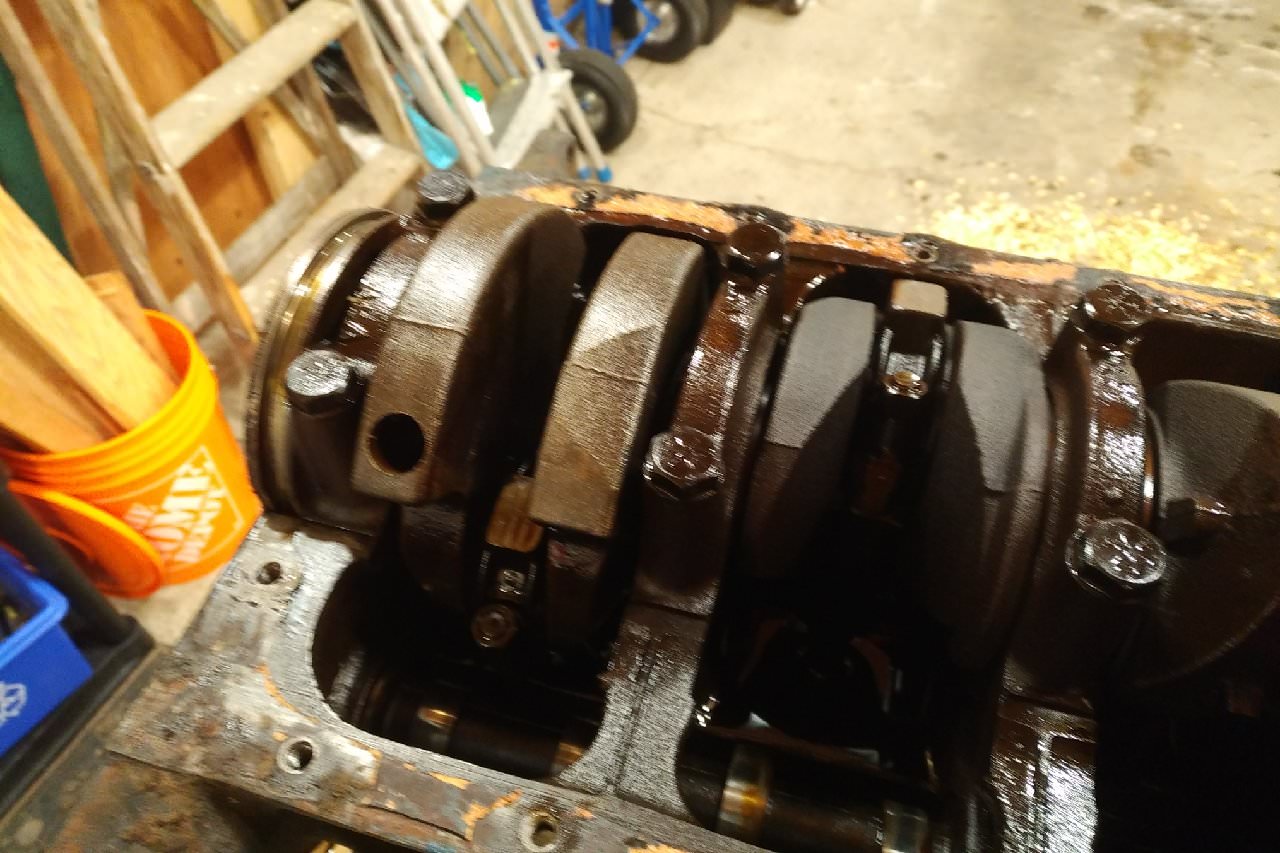
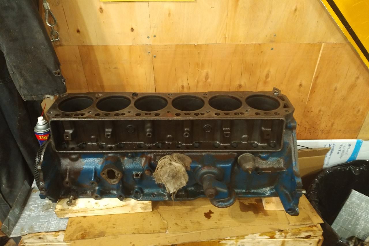
Got to spend a bit more time in the shop this weekend. Got all the pistons out and removed the crank.
Crank bearings were mostly decent (top bearing on rod 4 was rubbed past the copper in a small spot) and mains all looked good with little-to-no copper showing anywhere. Crank bearings all were stamped .010 on them, but I will get the micrometers out and see exactly what I'm working with.
Also got started on cleaning and degreasing the block and parts, but this takes a bit of time to do things right. Hopefully soon I can put all the paper towels and oily rags and floor dry away and start blueprinting things, and finally see what exactly I'm working with.
#27
11-20-2017, 10:25 AM

#28
11-24-2017, 10:00 AM
Join Date: Nov 2008
Posts: 106
Likes: 0
Received 0 Likes
on
0 Posts
Well the Offenhauser intake showed up yesterday, so it was a very good day. Definitely the most blingy part of the project.
Unfortunately I'm being held up waiting on some decent micrometers to measure the crank journals with, so I'm not able to order the rebuild kit yet.
Hoping this weekend to start cleaning the deck and head and checking for warping.
Unfortunately I'm being held up waiting on some decent micrometers to measure the crank journals with, so I'm not able to order the rebuild kit yet.
Hoping this weekend to start cleaning the deck and head and checking for warping.
#29
11-29-2017, 02:29 PM
Join Date: Nov 2008
Posts: 106
Likes: 0
Received 0 Likes
on
0 Posts
Well this weekend I pulled apart the head and started cleaning. For those who don't know, this stuff is called "Ed's Red" and it's used as a rifle cleaning solution. (Ed's Red Recipe: 1 part ATF, 1 part Acetone, 1 Part Paint Thinner, 1 Part Naptha/Kerosene.) I figured since it works so well for old crusty rifle bores, it would probably work just fine for cylinder heads.
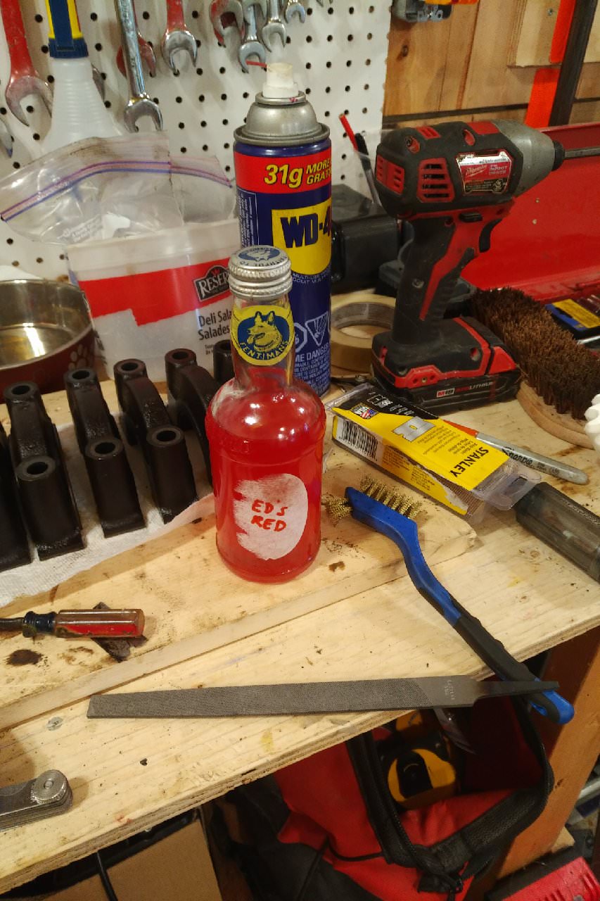
Started with this:
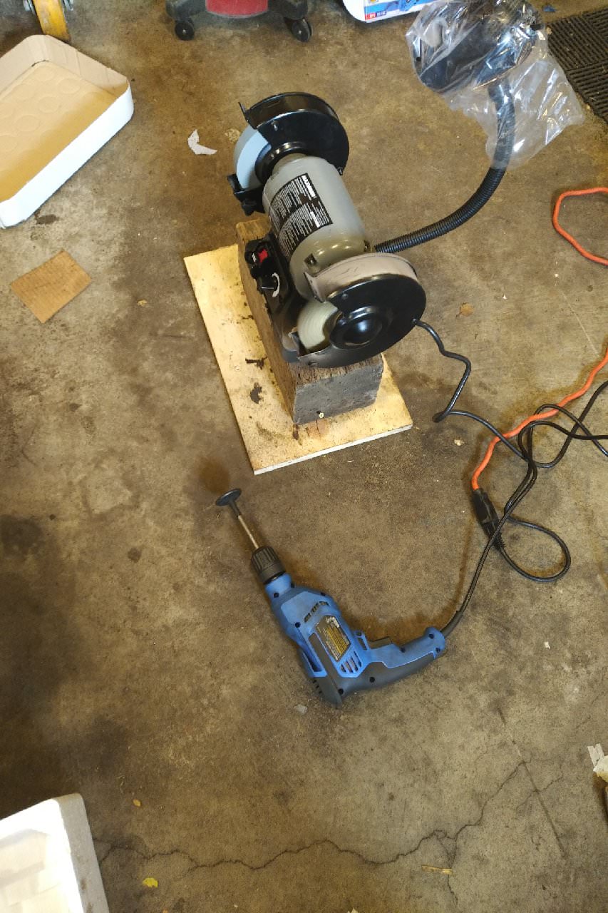
Then busted out these (Don't ask why the bench grinder isn't actually mounted on the bench...)
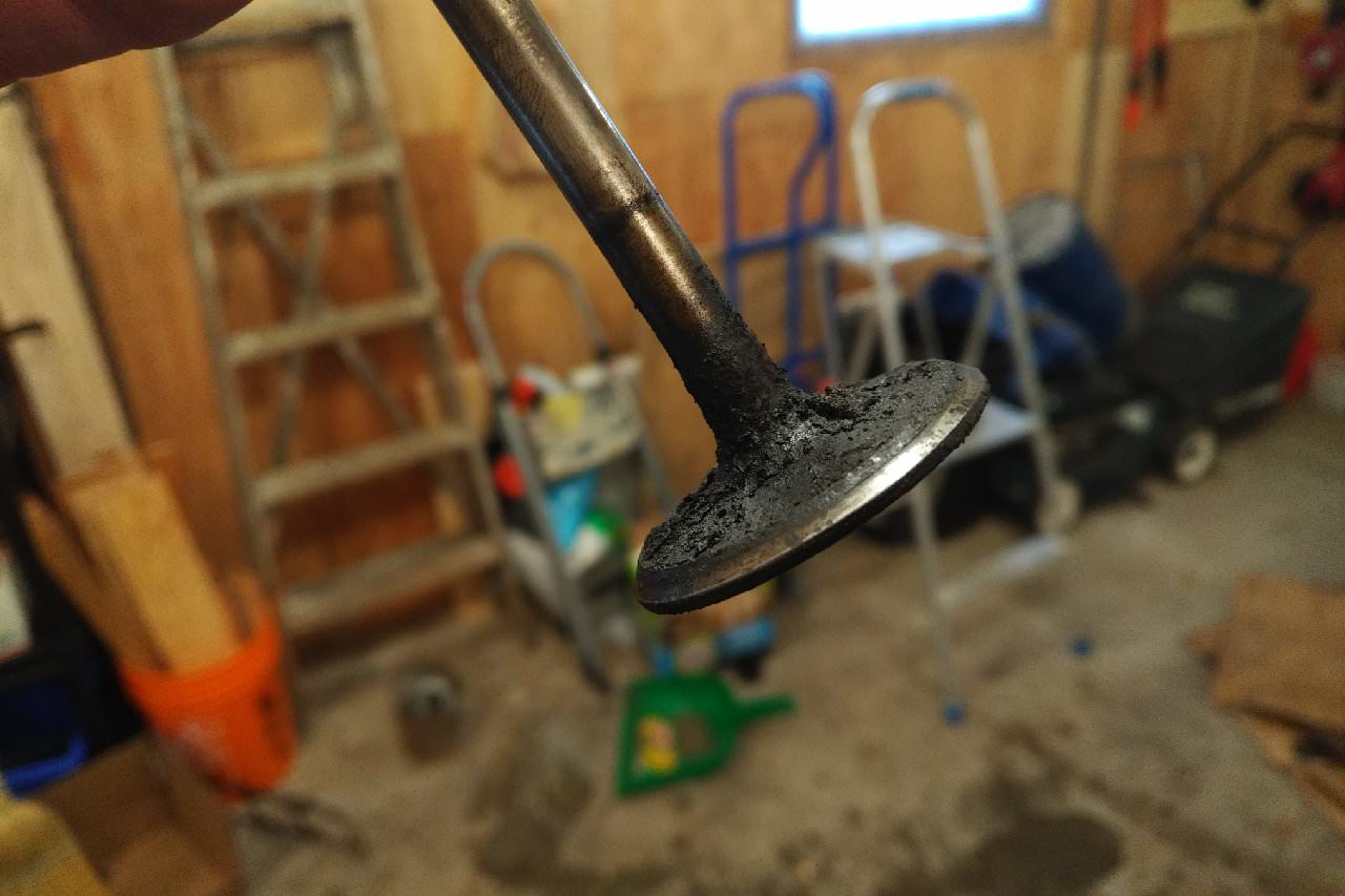
I was feeling inspired at this point, so figured I would start lapping in the valves. Didn't completely finish the job, but made some decent progress
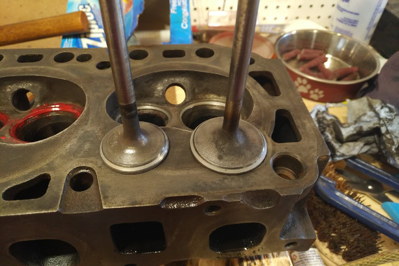
Cleaning up the inside of the heads where the valve seats are is tricky. A brass brush on a dremel works well. Just go slow, and don't force things. (Don't mind the red colour around the valve seats: that's nail polish "borrowed" from the wife. It's a poor man's Dykem. A Sharpie works just as well.)
I also checked the cylinder head deck for flatness using a straight edge and a feeler gauge. The service manual says that the deck can be out of spec by .006 6 inches in any direction. I found one specific spot by the #1 cylinder that was out of spec by .005, but I couldn't fit the .006 through. Nowhere else on the head could I fit the .005 through.
I did the same on the block, only this time using a .003 gauge. I couldn't find any specs for the block in terms of what is allowed, so went by some different specs that I knew off the top of my head (.003 = go, .004+ = no go). There was one little spot by the #2 cylinder on the diagonal that I could fit the .002 through, but that was it.
I don't know if this is allowed, but I'm going to plug these two videos that I found browsing around youtube. They do a great job of actually explaining what to do when you're overhauling an engine and messing around with heads. For me it was nice to see the process of determining whether a guy actually needs to get machine work done.
It's not for a Ford motor, but the theory is still the same.
Started with this:
Then busted out these (Don't ask why the bench grinder isn't actually mounted on the bench...)
I was feeling inspired at this point, so figured I would start lapping in the valves. Didn't completely finish the job, but made some decent progress
Cleaning up the inside of the heads where the valve seats are is tricky. A brass brush on a dremel works well. Just go slow, and don't force things. (Don't mind the red colour around the valve seats: that's nail polish "borrowed" from the wife. It's a poor man's Dykem. A Sharpie works just as well.)
I also checked the cylinder head deck for flatness using a straight edge and a feeler gauge. The service manual says that the deck can be out of spec by .006 6 inches in any direction. I found one specific spot by the #1 cylinder that was out of spec by .005, but I couldn't fit the .006 through. Nowhere else on the head could I fit the .005 through.
I did the same on the block, only this time using a .003 gauge. I couldn't find any specs for the block in terms of what is allowed, so went by some different specs that I knew off the top of my head (.003 = go, .004+ = no go). There was one little spot by the #2 cylinder on the diagonal that I could fit the .002 through, but that was it.
I don't know if this is allowed, but I'm going to plug these two videos that I found browsing around youtube. They do a great job of actually explaining what to do when you're overhauling an engine and messing around with heads. For me it was nice to see the process of determining whether a guy actually needs to get machine work done.
It's not for a Ford motor, but the theory is still the same.
#30
12-05-2017, 11:08 AM
Join Date: Nov 2008
Posts: 106
Likes: 0
Received 0 Likes
on
0 Posts
Well yesterday was a good day: The postman showed up with all sorts of goodies, including my new-to-me 1950's micrometers.
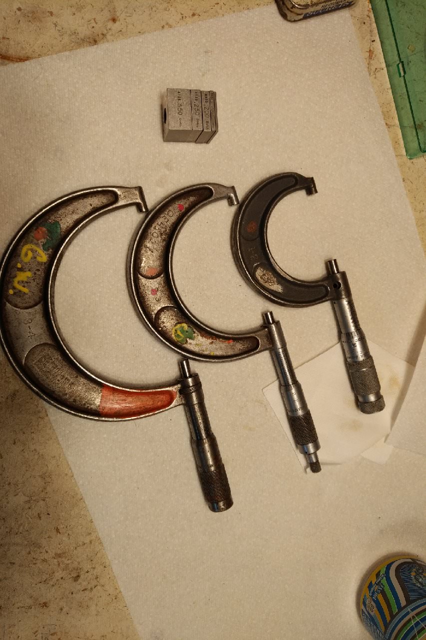
Calibrated them against some gauge blocks, and they were/are still in spec. So that's kind of fun.
Anyway, now that I had the proper tools, I got to measuring the crank journals last night, and everything mic'd within spec! My wallet was happy about that. The rod journals were definitely ground .010, so will need to pick up some .010 under bearings.
For the guys who might be doing this in the future, you can get by with just a 2-3" micrometer - no need for any others. However, I would recommend getting a 3-4" while you're at it for calibrating your dial bore gauge.
Speaking of dial bore gauge, I'm hoping to check all the cylinders tonight to see if they are overbored or not. Then I can finally order an engine rebuild kit (Ring size is the last piece of the puzzle.)