When you click on links to various merchants on this site and make a purchase, this can result in this site earning a commission. Affiliate programs and affiliations include, but are not limited to, the eBay Partner Network.
So I am looking to put in an aftermarket distributor-less ignition system. I have been checking out the 1986 EVTM on Gary's site. I have two questions:
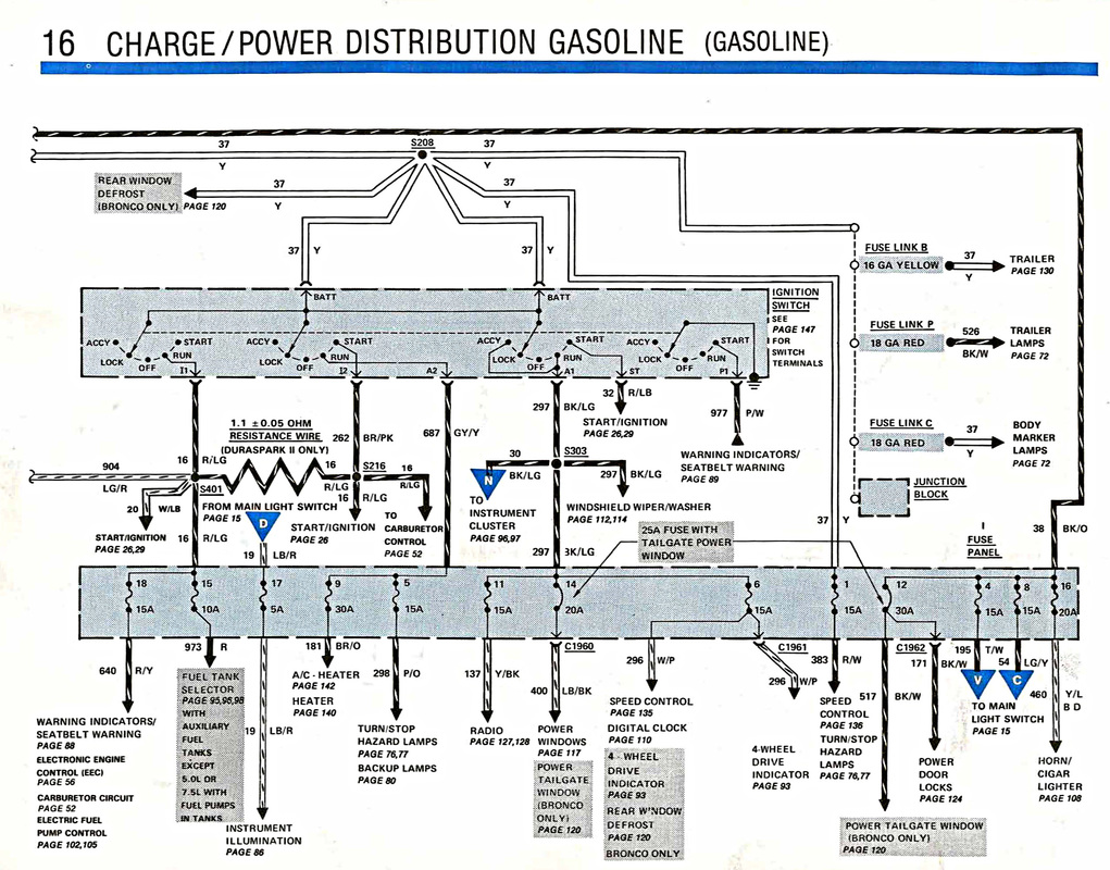
What is the purpose of the 1.1 ohm resistor wire on the start/run keyed switch?
And,
Since my new ignition box needs a start AND run circuit to feed it, which circuit do I use, the 16 or 20? Or does it matter?
Looks like the resistor (which is 1.1 ohm with a variance of +or- 0.05 ohms) is a security feature for duraspark 2 ignition needing a reading on 16 and 20 to start with the resistance dropping the voltage on 20 to tell the ignition unit its ok to start because the key was used (thus 20 or white/light blue? could be omitted with the new system). Use the brown/ pink for start, and the red/ light green for run it looks like those are the wires going to your current ignition module which you are deleting. If this is the correct diagram for your system the amperage for the other leads coming from the ignition switch may be overloaded with the aftermarket ignition system added to that part of the circuit.
The resistor drops current to the ignition coil in 'run' too keep it from overheating.
As was mentioned the stock wiring cannot provide enough power for many HEI units.
Most people use the stock DSII coil wire to trigger a 30A relay and use heavy gauge wire from the hot lug of the fender relay to power the HEI.
He said he is going to a distributorless ignition. If that is the case it will have coil packs or coil-on-plug, no distributor but a crank sensor and toothed wheel on the crank.
Study the switch, I think you will need to use two different wires so you will have power in start and run. Like was said, forget the resistor, it's just for the original ignition system and ignition coil to make it run cooler.
We see that #20 (W/LB going to the module) gets full power in run and resistor power at start, while 16 gets full power in start and resistor power in run.
I'm not sure what system (cop or cp) is going to be used, or how much current that system needs to fire reliably.
Triggering a simple relay with either the #20 or the #16 circuit would remove any doubt
I will be using a 2 coil pack system. Wiring shows a 12v source to be applied to both coils, the ignition module and the Ford EDIS module.
So I have two questions. First, should I remove the resistor to separate the 16 and 20 circuits, then splice both circuits together to the new equipment?
2: Should I NOT mess with the resistor, and add a dual relay system triggered by 16 and 20 to power the new equipment?
I would splice them together. However you want to do it. Find the resistor wire and wire a regular piece of wire around it, or whatever is the easiest way. You could leave the resistor in place if you just jump across it either at the resistor or wherever you can get to it.
Another option would be to add a single relay to power both coils and use the ignition #16 circuit coming to the old coil as-is. You're going to want fresh current going to those coils to help troubleshoot things down the road.
Another option would be to add a single relay to power both coils and use the ignition #16 circuit coming to the old coil as-is. You're going to want fresh current going to those coils to help troubleshoot things down the road.
Going by the diagram above, circuit 16 is only hot in start position.
Going by the diagram above, circuit 16 is only hot in start position.
Nope the #16 wire is hot during start and run. The run side will feed voltage only thru the resistor. The wire that would go to the original coil's positive terminal would be the #16 wire.
BUT... the #20 wire that is feeding from the #16 wire to the old ignition control module is resistor free, so you can be getting a full 12V there for the relay trigger if you feel the 9-10v coming from the coil circuit isn't enough. I guess it just really matters where you want to mount the relay and coils.
Coils will be mounted on the engine. I'm putting in a power distribution box with relays next to the battery. Here is a picture of the 84 EVTM. Looks like I can also use circuit 32.
Coils will be mounted on the engine. I'm putting in a power distribution box with relays next to the battery. Here is a picture of the 84 EVTM. Looks like I can also use circuit 32.
By the looks of it, circuit 32 is live only in start
Correct. But I was planning on using a start and a run circuit. I don't think it will hurt the ignition switch to have 12V sitting on the opposite potential.
Rezvani's Latest Post-Apocalytic Monster Is a Ford F-150 Raptor Underneath
Slideshow: Called the Fortress, the 850-horsepower pickup combines Raptor underpinnings with military-inspired features, survival equipment, and a starting price of $285,000.


 well that's embarrassing. .


