When you click on links to various merchants on this site and make a purchase, this can result in this site earning a commission. Affiliate programs and affiliations include, but are not limited to, the eBay Partner Network.
AMP Research Running Board Install on 2001 Excursion how to with pics
This is my first big post and i saw others wanted someone to put a how to together. I finally got around to installing my Amp Boards that have been sitting in the back of the Excursion for 6 months now. I never found a good install page for our Ex so thought I would make one to save whoever needs it a lot of time. I have a 2001 and bought the Super Duty Amp boards that also fit the Ex. It is a pretty easy installation except for the fact a lot of the directions didn't work for my Ex which made the 3 hour installation time Amp say it takes to maybe a 8 hour time within the last two days and a very unhappy Wife..... Anyways hope it helps and I'll try to answer questions the best I can. We have twin baby boys and a 2 year old so my time is limited. I am still doing the finishing touches.
Here it is:
First step is unmount the factory running boards. I used my impact drill with a 1/2 deep socket to take out all the bolts and left the center one for last for easy dismount. Mine had lights so you have to disconnect the light harness.
1/2" socket
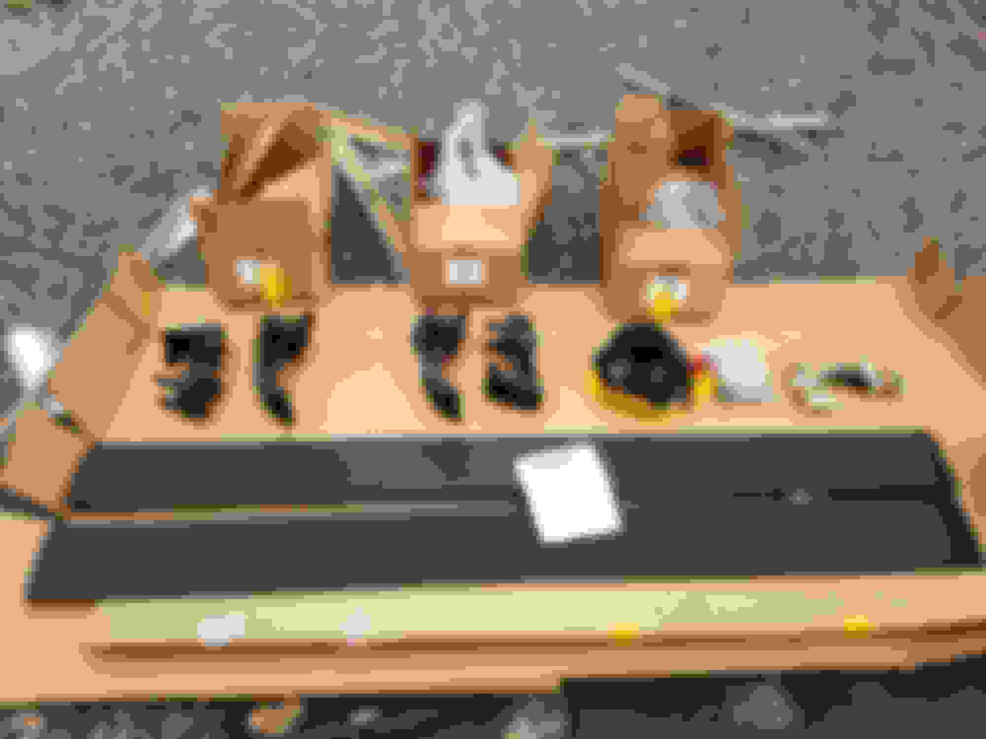
First step was to mount the two motors on the arms. Just set it on the arm, line up the holes and tighten the 3 screws.
Next is for EXCURSION ONLY, cut off 1/4 " off the top of all 4 arms ( Above the green tape in this pic). This is very hard metal. Used a 4" metal blade on my electric grinder. (Wear glasses and gloves!)
This is what they look like cut, grind edges down or use a file as edges are sharp. I then painted all four cuts with black rustolium paint.
Now I really don't know if cutting these was really necessary, you'll see in later pics..
This is the hardware. Directions are not clear on what washers to use where but you use the long hex head bolts with the black washers on the two top holes of the mounting arms and the Allen head stainless bolts with stainless washers.
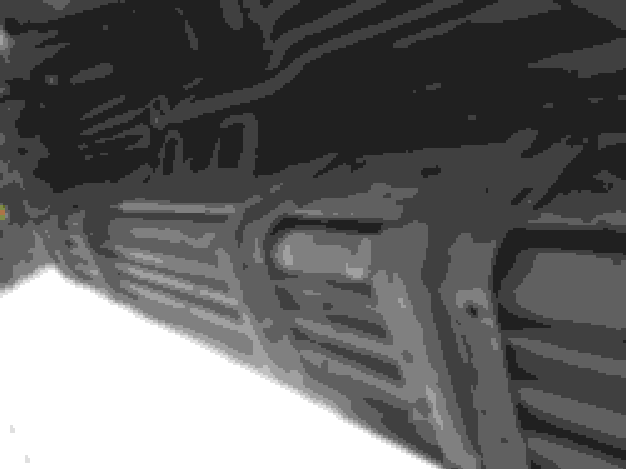
The front arms mount where the second bracket was mounted from the factory boards (from the front) and the rear mount is where the last bracket from the facrory boards. On both of the rears there is only 3 holes available for the mounting of the rear arm so i drilled a fourth hole. Pic below before I drilled the hole.
The hex heads are the upper two and install from under the truck outwards and the stainless install from outside the truck inwards.
This is why I don't know if cutting the 1/4" was necessary as you see there is room between the top of the arm and the underbody.. Our well..
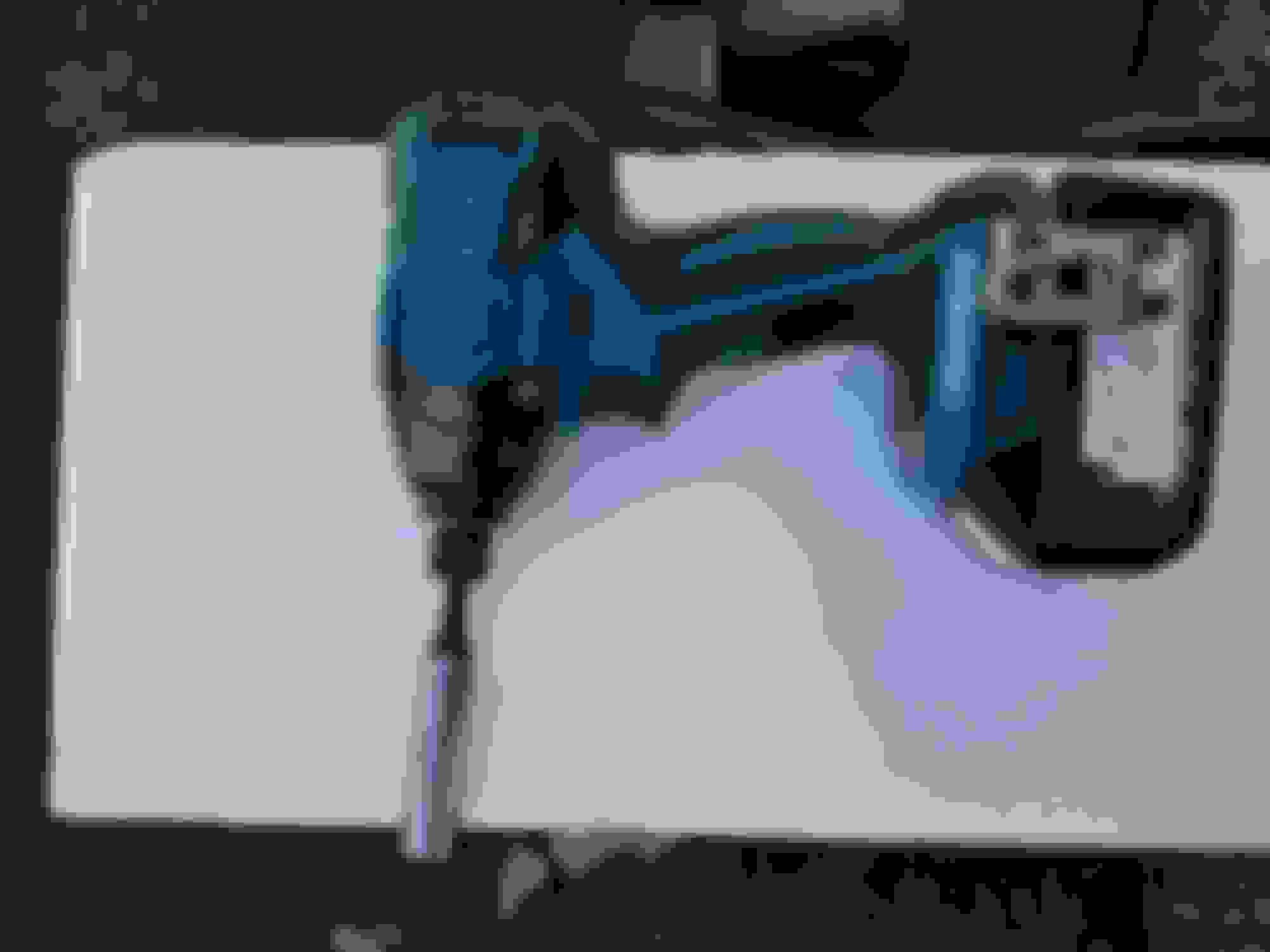
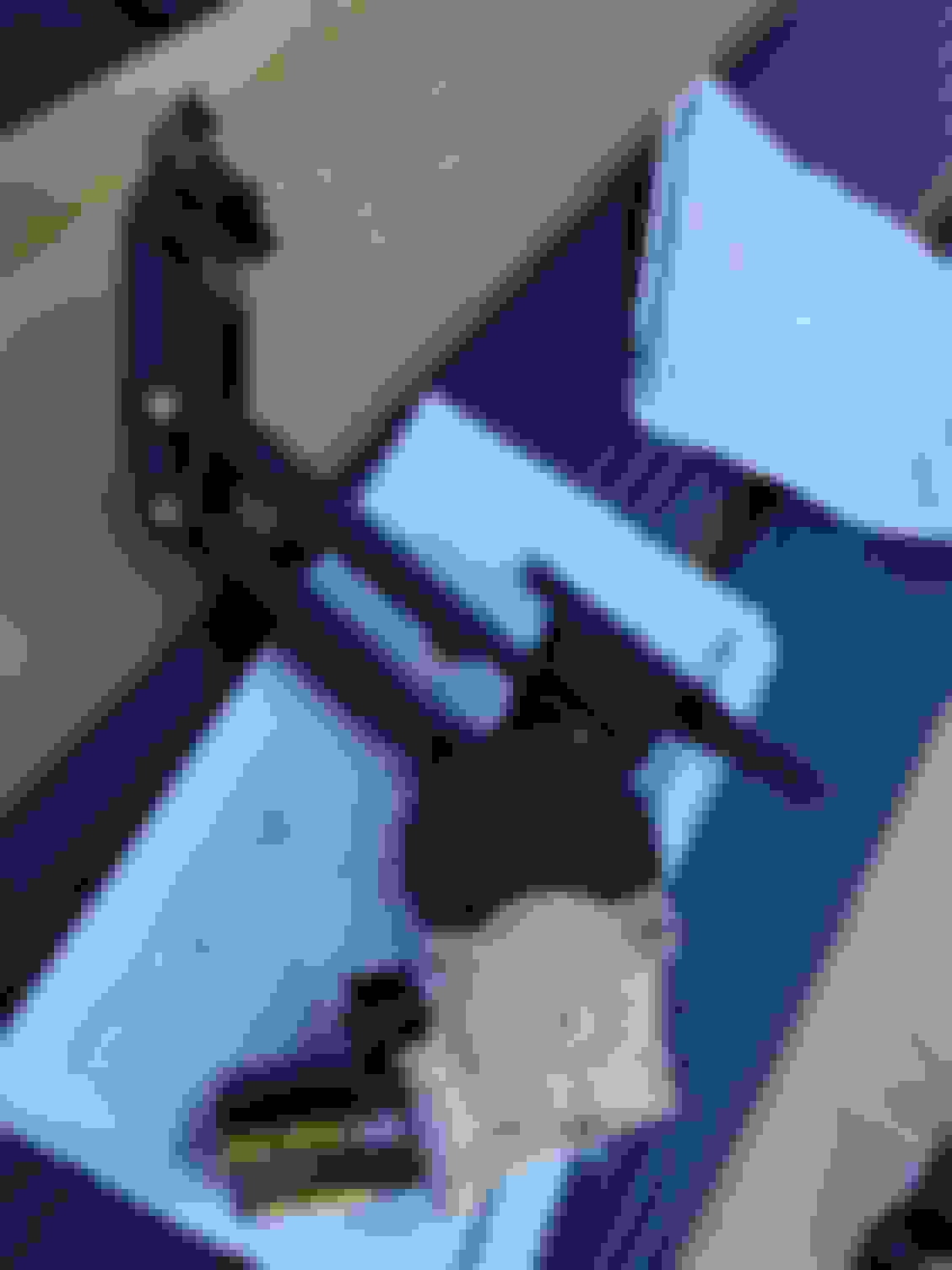
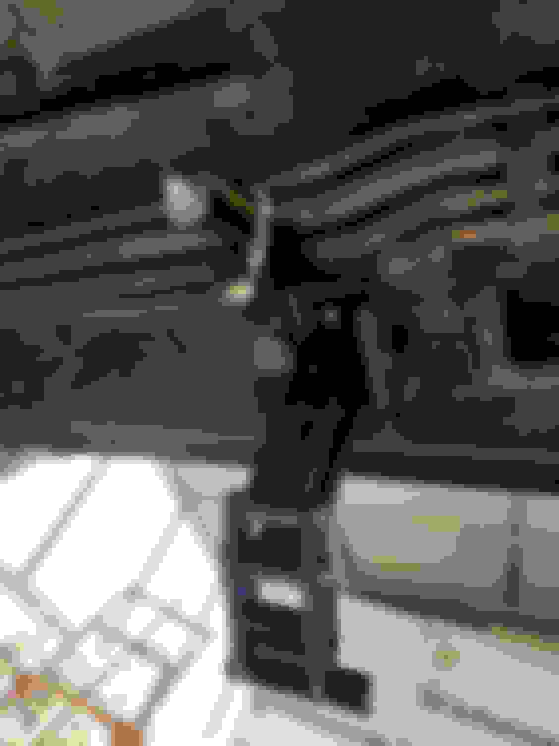
okay so this above picture is where I started having issues with directions. it says to mount the motor drive arm at the rear of the vehicle. That doesn't work with my Ex as you can see it was hitting the under body on the drivers side. On the passenger side we have these lines in the way which are rear air conditioning I believe and the motor on the arm was definitely hitting these. Pic below of the lines with the non motor arm installed.
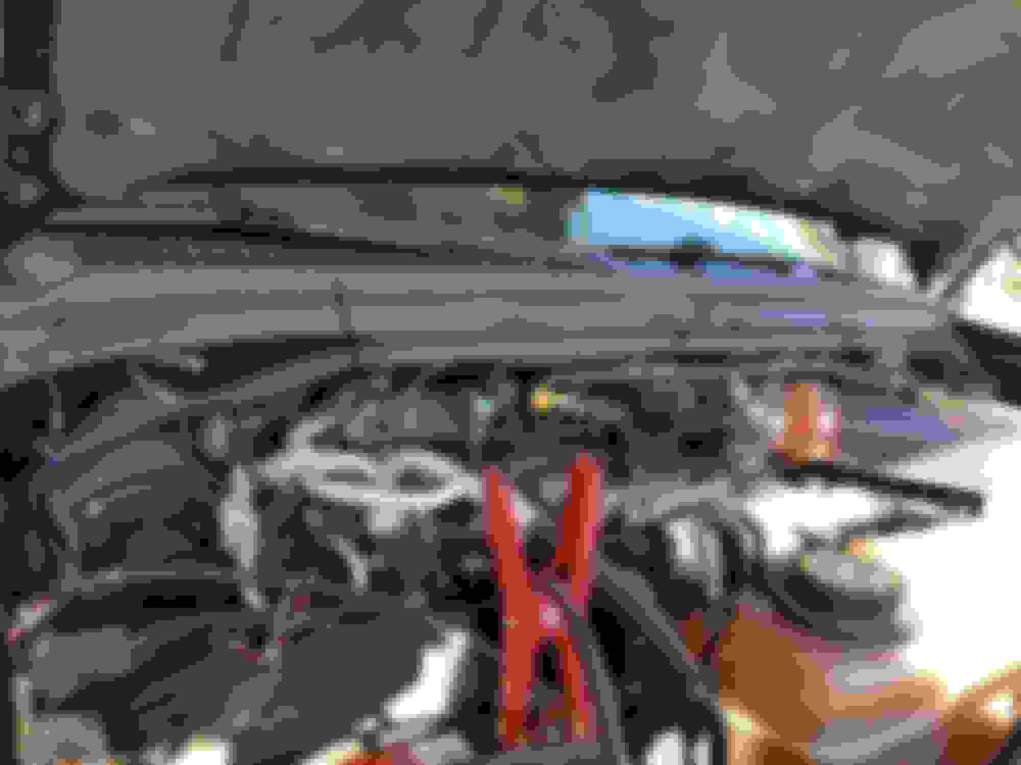
So I decided to move the motor drive arms towards the front of the vehicle and there is amply space for each motor without hitting anything.
Pic.above is passenger side front with motor. These lines are not in the way up front. Also the cable provided wouldn't reach the motor arms if you mounted them in the back like the directions said so I guess it was meant to be.
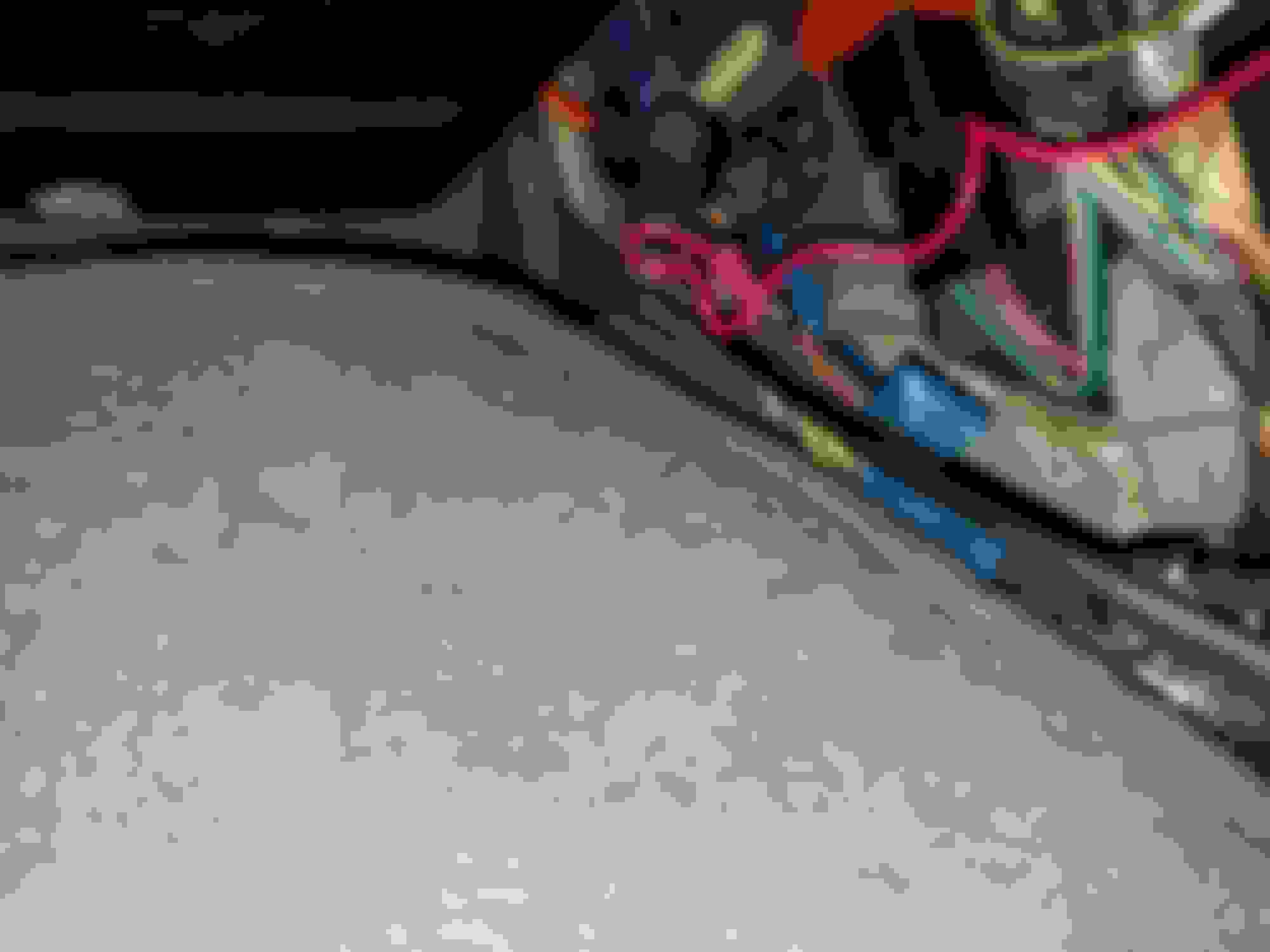
pic above us just to show how I ran the wiring from the battery. I don't have pics of this but can take some if needed but the amp control module you zip tie to the inner fender behind the battery. The cable plugs into that and has a positive wire with 30amp fuse going to battery and also a negative. out.of the control module the wiring tees off, one for the driver side where you can see in the pic I went across the top where the I trimmed zip ties are and dropped it down above the drivers front fenderwell. the other part of the tee just goes to the passenger side.and again I dropped it.down the passenger side fender well. The wire comes with the wire loom and a purple wire ran with it to both sides of the vehicle. Drivers side below
Passenger side below
these wires come out underneath the vehicle and just plug right in to the motors connector. The purple wire also is underneath the vehicle and you have to poke a hole in a plastic/rubber grommet underneath where both the drivers and passengers floor mats are and run the purple wire up through that grommet under the carpeting and to your door sill.
Next step is taking the provided red wiring and using the posi tap connectors that are also included you have to tap into the door lock wiring. This is where the directions say to take your door panel off and speakers to find the bundle of wire below and to the right of the speaker coming from the lock and tap into the wire there and run the red wire through the door through the rubber sleeve and into the cab.. Pic below is where the wiring is located by speaker on passenger side. It is pretty much same for drivers side.
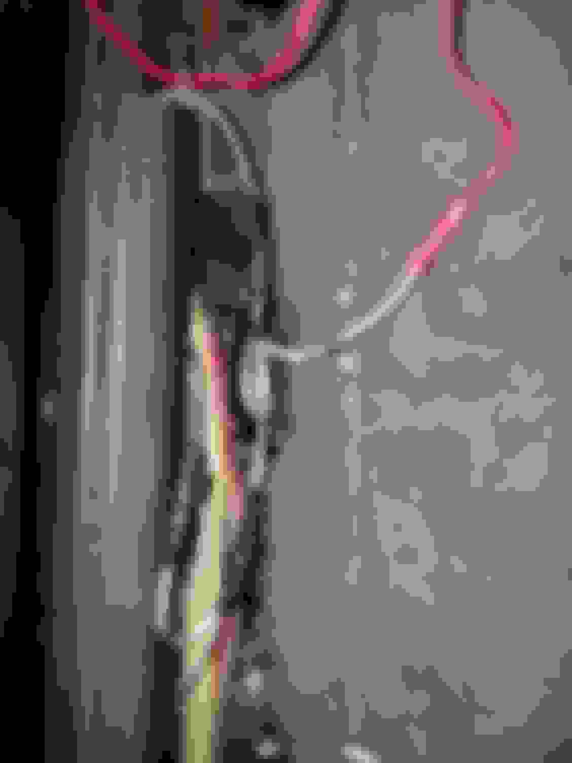
That seemed like it would be difficult so I just looked for he correct wires inside the cab and tapped into them there. Now another thing that is misleading from the directions it says to tap into the pink and black stripe wire on drivers side and the black and pink stripe wire and the passengers side. This is incorrect atleast on my 2001 Drivers side door lock wire you want on tap is the All black with pink stripe and passenger door lock wire you want to tape is black with a purple stripe. I spent a lot of time trying to figure this out so your welcome! And here is the pics where to find them below. First drivers side, above where steering column comes in you'll see a bundle of wires and that's where I tapped in using the red wire and posi taps. Then run the wire to your left and to the drivers side sill plate.
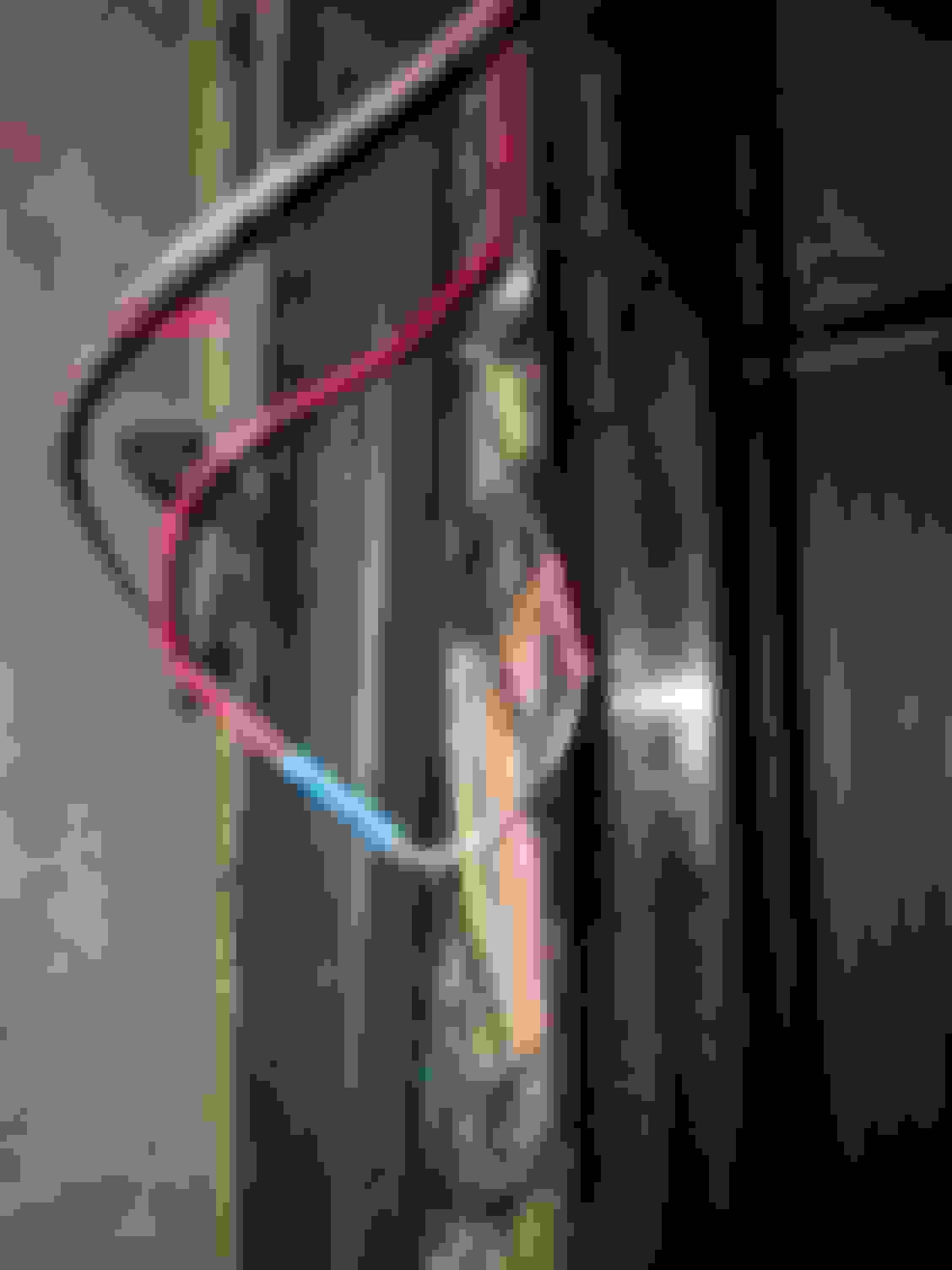
Once you get the red wire to your sill plate you'll now have your purple and red wires there. You then connect a double diode (looks like a Y) wire's blue connector to the purple wire you ran from underneath (2 doubles are included but this year Ex needs one double and you take apart the other double diode to make 2 single ones) and connect one of the double diodes to the red wire you just ran. Now you have one part of the "Y" left. You have to find a black with white stripe wire that runs down the sill plate to the rear doors. Once you locate that wire you cut it. Then you take a single diode you made from splitting the double diode and connect the single diode to the black with white stripe wire (towards the front of the vehicle) you just cut and connect it two the last part of the "Y" from he double diode along with the other half of the black with white stripe wire you cut. Yes this is probably confusing so pics below.
For the passenger side you tap into the black with purple stripe wire located in kick panel next to the fuel shutoff botton. (This is the one that was a pain for me to find)
So same thing once you tap that wire run the red wire to the passenger door sill area where your purple wire is already and also locate the same black wire with white stripe you cut on he drivers side and do he same and cut it. (Be careful there is a brown wire that looks black with a white stripe but it's a thicker guage) You take the other single diode you made from the 2nd double diode sent and connect your purple and red to one end of that single diode along with the black and white striped wire (from rear of vehivle) The other end connects to the other half of the black and white striped wire (closest to the front of vehicle). pics below.
After these confusing connections you simply hook the posited and negative cables up to the battery and put he 30amp fuse in and open and close your doors and see the motor drive arms go down and up when you open the doors. Next and lastly connect the boards with 4 Allen screws on each side from underneath the boards into the arms. Then watch your boards come down when you open and disappear when you close.
This is all I have right now as it got dark and my phone died so I'll try to add some more pics tomorrow of the finished product which is freaking awesome. Sorry for such a long post and if this post has errors as im tired its 1:30am and I'm doing this from my phone with my son sleeping next to me. I hope this helps someone out there and maybe you can install with in the 3 hours suggested!
Great write-up...thanks for taking the time and effort to do so!
I'm wondering if there's a specific part # for the Excursion that could explain the issues you had with the installation...still...all's well that ends well.
One of the things keeping me from doing these is drilling that one hole in the punch weld...
Wow, great post. i wish i had seen this before dropping my Amp boards off at the 4wd shop for them to install. I was a little nervous on the electrical. Also, your frame and underbody are in great shape! no rust like most ex's I've seen.
Do you mind sharing the part #? I have an 2016 F250 i�m selling and want to put the amp power steps on my excursion but the shop who did it said the excursion uses another part and they aren�t compatible 🤔
they gave me 75104-01A for Excursion & what i have is 76234-01A
thanks!!! The pictures help a lot. 👍🏻👍🏻👍🏻
Originally Posted by dolphan02
This is my first big post and i saw others wanted someone to put a how to together. I finally got around to installing my Amp Boards that have been sitting in the back of the Excursion for 6 months now. I never found a good install page for our Ex so thought I would make one to save whoever needs it a lot of time. I have a 2001 and bought the Super Duty Amp boards that also fit the Ex. It is a pretty easy installation except for the fact a lot of the directions didn't work for my Ex which made the 3 hour installation time Amp say it takes to maybe a 8 hour time within the last two days and a very unhappy Wife..... Anyways hope it helps and I'll try to answer questions the best I can. We have twin baby boys and a 2 year old so my time is limited. I am still doing the finishing touches.
Here it is:
First step is unmount the factory running boards. I used my impact drill with a 1/2 deep socket to take out all the bolts and left the center one for last for easy dismount. Mine had lights so you have to disconnect the light harness.
1/2" socket
First step was to mount the two motors on the arms. Just set it on the arm, line up the holes and tighten the 3 screws.
Next is for EXCURSION ONLY, cut off 1/4 " off the top of all 4 arms ( Above the green tape in this pic). This is very hard metal. Used a 4" metal blade on my electric grinder. (Wear glasses and gloves!)
This is what they look like cut, grind edges down or use a file as edges are sharp. I then painted all four cuts with black rustolium paint.
Now I really don't know if cutting these was really necessary, you'll see in later pics..
This is the hardware. Directions are not clear on what washers to use where but you use the long hex head bolts with the black washers on the two top holes of the mounting arms and the Allen head stainless bolts with stainless washers.
The front arms mount where the second bracket was mounted from the factory boards (from the front) and the rear mount is where the last bracket from the facrory boards. On both of the rears there is only 3 holes available for the mounting of the rear arm so i drilled a fourth hole. Pic below before I drilled the hole.
The hex heads are the upper two and install from under the truck outwards and the stainless install from outside the truck inwards.
This is why I don't know if cutting the 1/4" was necessary as you see there is room between the top of the arm and the underbody.. Our well..
okay so this above picture is where I started having issues with directions. it says to mount the motor drive arm at the rear of the vehicle. That doesn't work with my Ex as you can see it was hitting the under body on the drivers side. On the passenger side we have these lines in the way which are rear air conditioning I believe and the motor on the arm was definitely hitting these. Pic below of the lines with the non motor arm installed.
So I decided to move the motor drive arms towards the front of the vehicle and there is amply space for each motor without hitting anything.
Pic.above is passenger side front with motor. These lines are not in the way up front. Also the cable provided wouldn't reach the motor arms if you mounted them in the back like the directions said so I guess it was meant to be.
pic above us just to show how I ran the wiring from the battery. I don't have pics of this but can take some if needed but the amp control module you zip tie to the inner fender behind the battery. The cable plugs into that and has a positive wire with 30amp fuse going to battery and also a negative. out.of the control module the wiring tees off, one for the driver side where you can see in the pic I went across the top where the I trimmed zip ties are and dropped it down above the drivers front fenderwell. the other part of the tee just goes to the passenger side.and again I dropped it.down the passenger side fender well. The wire comes with the wire loom and a purple wire ran with it to both sides of the vehicle. Drivers side below
Passenger side below
these wires come out underneath the vehicle and just plug right in to the motors connector. The purple wire also is underneath the vehicle and you have to poke a hole in a plastic/rubber grommet underneath where both the drivers and passengers floor mats are and run the purple wire up through that grommet under the carpeting and to your door sill.
Next step is taking the provided red wiring and using the posi tap connectors that are also included you have to tap into the door lock wiring. This is where the directions say to take your door panel off and speakers to find the bundle of wire below and to the right of the speaker coming from the lock and tap into the wire there and run the red wire through the door through the rubber sleeve and into the cab.. Pic below is where the wiring is located by speaker on passenger side. It is pretty much same for drivers side.
That seemed like it would be difficult so I just looked for he correct wires inside the cab and tapped into them there. Now another thing that is misleading from the directions it says to tap into the pink and black stripe wire on drivers side and the black and pink stripe wire and the passengers side. This is incorrect atleast on my 2001 Drivers side door lock wire you want on tap is the All black with pink stripe and passenger door lock wire you want to tape is black with a purple stripe. I spent a lot of time trying to figure this out so your welcome! And here is the pics where to find them below. First drivers side, above where steering column comes in you'll see a bundle of wires and that's where I tapped in using the red wire and posi taps. Then run the wire to your left and to the drivers side sill plate.
Once you get the red wire to your sill plate you'll now have your purple and red wires there. You then connect a double diode (looks like a Y) wire's blue connector to the purple wire you ran from underneath (2 doubles are included but this year Ex needs one double and you take apart the other double diode to make 2 single ones) and connect one of the double diodes to the red wire you just ran. Now you have one part of the "Y" left. You have to find a black with white stripe wire that runs down the sill plate to the rear doors. Once you locate that wire you cut it. Then you take a single diode you made from splitting the double diode and connect the single diode to the black with white stripe wire (towards the front of the vehicle) you just cut and connect it two the last part of the "Y" from he double diode along with the other half of the black with white stripe wire you cut. Yes this is probably confusing so pics below.
For the passenger side you tap into the black with purple stripe wire located in kick panel next to the fuel shutoff botton. (This is the one that was a pain for me to find)
So same thing once you tap that wire run the red wire to the passenger door sill area where your purple wire is already and also locate the same black wire with white stripe you cut on he drivers side and do he same and cut it. (Be careful there is a brown wire that looks black with a white stripe but it's a thicker guage) You take the other single diode you made from the 2nd double diode sent and connect your purple and red to one end of that single diode along with the black and white striped wire (from rear of vehivle) The other end connects to the other half of the black and white striped wire (closest to the front of vehicle). pics below.
After these confusing connections you simply hook the posited and negative cables up to the battery and put he 30amp fuse in and open and close your doors and see the motor drive arms go down and up when you open the doors. Next and lastly connect the boards with 4 Allen screws on each side from underneath the boards into the arms. Then watch your boards come down when you open and disappear when you close.
This is all I have right now as it got dark and my phone died so I'll try to add some more pics tomorrow of the finished product which is freaking awesome. Sorry for such a long post and if this post has errors as im tired its 1:30am and I'm doing this from my phone with my son sleeping next to me. I hope this helps someone out there and maybe you can install with in the 3 hours suggested!

 11-04-2016, 03:35 AM