When you click on links to various merchants on this site and make a purchase, this can result in this site earning a commission. Affiliate programs and affiliations include, but are not limited to, the eBay Partner Network.
The diff is leaking slowly and im wanting to fix it, the issue is it appears that i will need to pull the whole axle to do anything and also the leak is not in the main gasket seal. are there any options I have besides removing the whole rear end or do I just need to suck it up and redo all the gaskets?
Looks like it's the pinion seal. That can be changed without taking the axle apart. Pull the driveshaft and pinion yoke, then replace the seal and put it back together.
That's not the recommended way, as it is difficult to get the proper bearing load set again, but it can be and has been done many MANY times.
2X. But I'll add that the lock nut that holds the pinion yoke on is REAL tight. A shop should really do it.
From another Forum:
Pinion Nut Torque value on a ford 9"
Most pinion nuts are tightened with new crush sleeve untill the correct rotational torque is achieved not nessacarily a torque spec the spec varries with old and new pinion bearings.
If you use a solid spacer, then typically 175 ft/lbs. If you're using a crush sleeve, then as noted.
Wiggle the pinion up and down and back and forth side to side to see if there is any play. Worn bearing allow a pinion to move slightly and then wear out a seal. If the pinion doesn't move like I described then it is just a worn seal. If it does move then the new seal won't last long.
....I say "mostly" how to do this because this is just a 'core' 3.50 geared, 31-spline, 4-pinion Traction-Lok differential, 9-inch 3rd member I have in my stash of parts. It wouldn't make sense to put a new driving pinion seal in it when the rest hasn't been gone through.
--moving along....
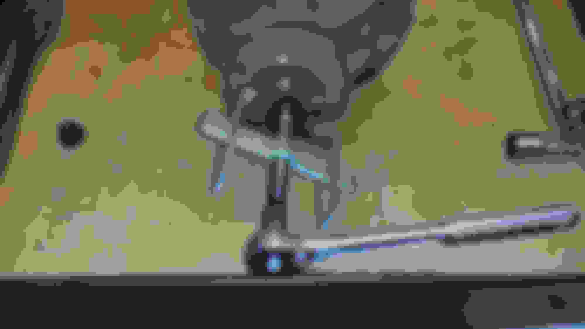
The first thing to do, after the driveshaft has been detached, is to take a paint pen and make a reference mark on one half of the tip of the threaded driving pinion stem, across one side of the pinion nut, onto the companion flange (the object the driveshaft attaches to) and onto the pinion support housing. The mark should be in a straight line on all of these.
Take a 1-1/16" socket and slide it up on the nut and make a reference mark on it that lines up with the reference mark previously made on the 3rd member.
Before we go any further, UNLESS you are installing NEW pinion bearings and races too, DO NOT USE AN IMPACT WRENCH to take the nut loose!! The rapid impacts from an impact wrench can cause the roller bearings of the pinion to violently chatter which can cause the surfaces of the roller bearings and the races to brinell. --This is a hand tools ONLY procedure.
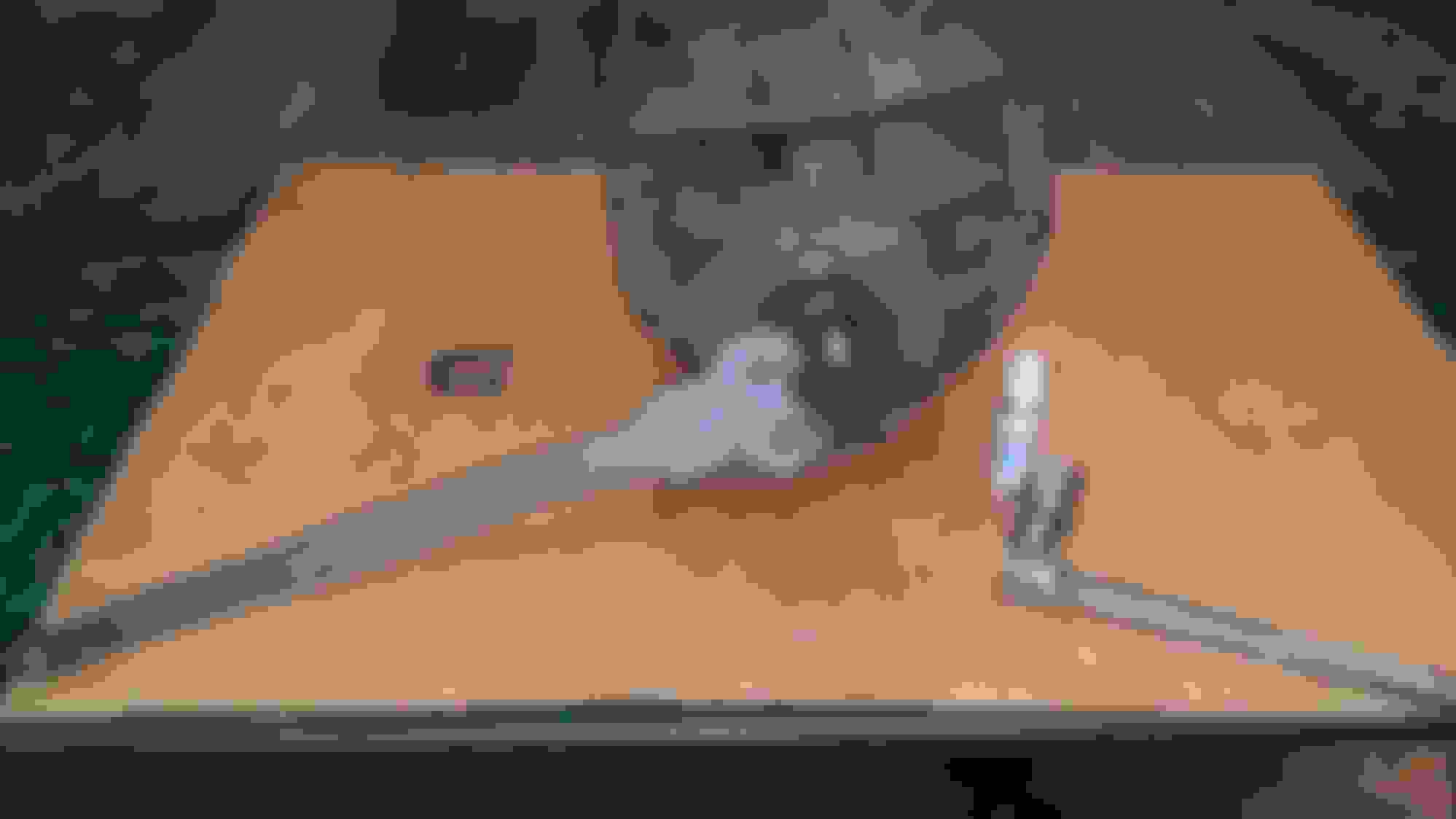
You'll need some means of holding the companion flange steady while you break the nut loose. This is a crude but very effective tool I made over 20 years ago just for this purpose. It will fit either 1310 or 1330 flanges just by flipping it around to the appropriate studs sticking out both sides of the head.
Before you take the nut loose, jot down on a piece of paper where your reference mark is oriented (in this case, it's at the 12:00 o'clock position). Slide your breakover bar/socket onto the nut, with the reference mark on the socket indexed to the reference mark on the nut.
Break the nut loose (CCW direction) and count the number of revolutions the reference mark on the socket goes past the reference mark on the companion flange. --after the nut is broken loose and backed off for a bit, you can probably loosen the nut the remaining distance by hand. In this case, The nut stopped just short of 16 full revolutions before it would come off the threaded stem of the pinion. The nut/reference mark is shown at the point the nut will come off the threads of the pinion.
Note that the reference mark on the nut (in this example in photo immediately above) is at about the 1:00 o'clock position). This position (or whatever yours ends up being) needs to be written down because this will be your starting point when you go to put the nut back on --after the new seal has been replaced and the companion flange put back on.
The companion flange is now ready to be removed from the pinion to gain access to the offending seal.
And just like that, it's off.
No pictures beyond this point but, remove the old seal. Make sure to clean the bore of dirt and oil where the seal seats into it (Acetone works very good for this). Take the new seal, apply a thin layer of Permatex Ultra Black RTV to the outer perimeter of its metal shell, take a little fresh gear oil and apply it to the rubber lip of the new seal and drive the seal into the bore.
Clean the splines and threads of the pinion with acetone. Apply some RTV in a ring around the pinion splines, clean the splines on the companion flange, align the reference mark of the companion flange and slide it onto the pinion.
Put some Loctite on the threads of the pinion and place the nut on the stem with the reference mark oriented to the location it was in when it came off the threaded pinion stem (refer back to your notes of what this position was).
Tighten the nut, counting the revolutions previously listed in your notes. Grab the companion flange and see if there is any up or down or side to side movement in it. If there is, tighten the nut a 1/16th to 1/8th turn and check the flange again, until there's no wiggle movement in the flange. It's not unusual to have to go some distance past the original number of revolutions it took to remove the nut but, it shouldn't be a very significant amount more.
If you go too far tightening the nut, it will compress the crush sleeve too much and the 3rd member will have to have a new crush sleeve and the preload and backlash will have to be resetup. --the only exception to this is if your 3rd member has a solid pinion spacer and not a crush sleeve. Solid spacers are not very common but crush sleeves are. Chances are very great your 3rd member will have a crush sleeve so, be careful of what you're doing.
Jofes, how about Ultra? It is all there.
He is our rear end guy. Price: $0.
Sorry, Ultra.
Oh, I see how it is. Now, I'm being called the resident ***. I can take a hint. ....I thought we were tighter than that. Ha ha
The procedure I previously described is just one I've used numerous times that has always worked for me, when changing out a leaky pinion seal. Hopefully, it'll work for anyone else who chooses to use and follow the instructions given.
no more Olestra chips! but in all seriousness thank you Ultra, I'm going to keep this thread on my list for when it's time to mess with the Diff
You're welcome and I'm glad if this will help you (or anyone else) that has a truck with a leaky pinion seal.
If you've aquired one of these old trucks, it's really a good idea to just go through and replace the pinion seal, axle seals, axle bearings, the 3rd member-to-housing gasket (if you have a Ford 9-inch rear end --Dana rear ends don't have a removable 3rd member) and put fresh gear oil in it.
If the old axle bearings or seals go out on you, it probably isn't going to happen while you're sitting in your own driveway/shop/garage. It's going to happen at the worst possible time and at the worst possible place, far from home.
Thanks Ultra, for that great step by step info pack. How do you do a leaking pinion seal on a Dana 60, if the third member is not removable? Is it basicley as simple as just remove the yoke and then the seal?
Rezvani's Latest Post-Apocalyptic Monster Is a Ford F-150 Raptor Underneath
Slideshow: Called the Fortress, the 850-horsepower pickup combines Raptor underpinnings with military-inspired features, survival equipment, and a starting price of $285,000.