When you click on links to various merchants on this site and make a purchase, this can result in this site earning a commission. Affiliate programs and affiliations include, but are not limited to, the eBay Partner Network.
Thank you for all the replies and kind words. It will be a while before I can drive the truck and test the brakes, but I hope to have the disc brake mod finished in a week or so. I did have a few minutes today to measure the pilot on the hubs that locate the drum. I will use that pilot to locate the flange that the rotor will bolt to. I was surprised to see a .010" difference between the two hubs. A third hub that I have the rotor bolted to now, is even larger, as I had to bore the flange out to fit it. This isn't going to be an issue on my conversion, I can remachine the hubs or machine the flanges to fit them. It may pose a problem though if I machine a kit for another members truck. The flange could be machined with a large enough bore to fit any hub and when it is installed on the hub, indicated in to run true. Although a .010" to .015" difference in hub diameters would mean that the rotor could possibly run out .007", maybe that is within the tolerance range on these big rotors.
Thanks again, Mark
Joe, I am keeping the original 5 hole pattern as I already have a set of 19.5 wheels. I am using the 10 hole rotor so the bolts for the rotor won't interfere with the 5 bolts that bolt the drum to the hub. I will use the drum mounting holes to bolt on the spacer that the rotor will bolt on to. If I had realized earlier that my front drums were not turnable, I probably would have changed the rear axle to a '70s 1 ton axle and modified the front to use 8 hole hubs and disc brakes from a late '70s 1 ton also. Then I could have used 16" tubeless wheels and tires. Although, adding the cost of changing the rear axle, I may not have saved any money going to the 8 hole wheel. I know I would have had a similar amount of machine time modifying the front for the 1 ton brakes.
Mark
Thanks for the explanation, when I saw the 10 hole I thought you were changing lug numbers, but this will work with the 5x8 pattern. Will you have to install longer studs or will the originals still be long enough?
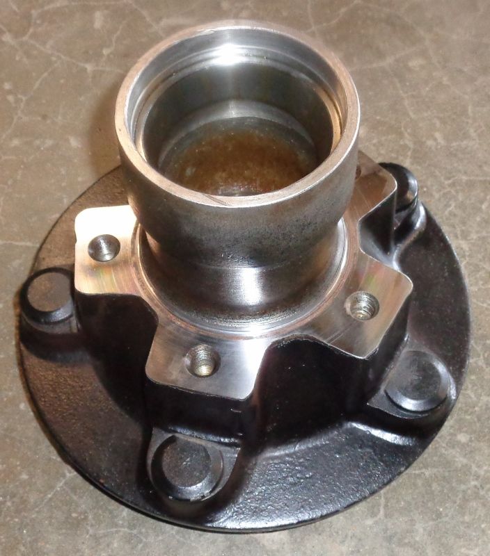
Joe, The hub has 5 holes on the back side that the drum bolted to. The hubs pre '48 had a different drum that was held in place by the lug bolts. Here is a photo of one of my hubs.
Mark
OH-FORD, Thank you for your kind words. The front axle assembly is the same '48-'52 F4-F6, so this conversion would work on your F6.
Thanks again, Mark
OH-FORD, Thank you for your kind words. The front axle assembly is the same '48-'52 F4-F6, so this conversion would work on your F6.
Thanks again, Mark
No problem Mark, Always happy to give credit where credit is do. If you decide / would be willing to produce additional conversion sets, definitely let me know.
I was able to work on the brakes today, here are a few photos.
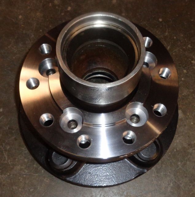
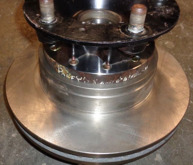
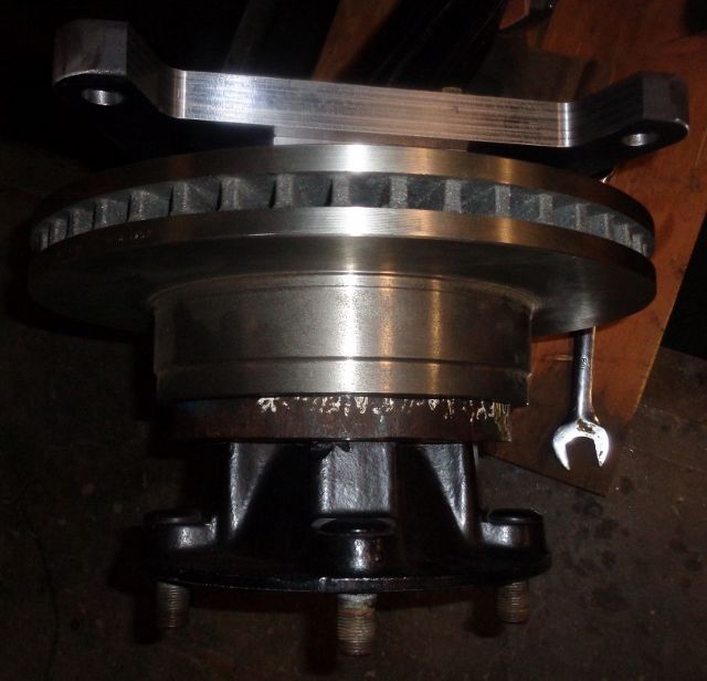
This is the rotor mounting flange setting in place on the hub. This flange is machined from 8" diameter 4150 heat treated steel.
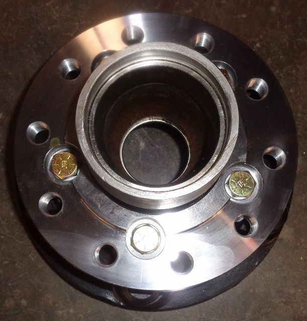
This is the flange bolted in place with grade 8 hex head cap screws.
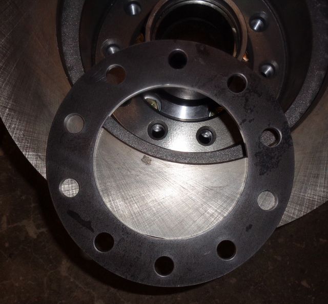
This is the rotor in place on the flange. There is a pilot on the flange that fits the center hole of the rotor. The I.D. of the flange fits the pilot on the hub for the original drum. I did machine the pilot and face of the hub between centers to make sure they were true and the same size.
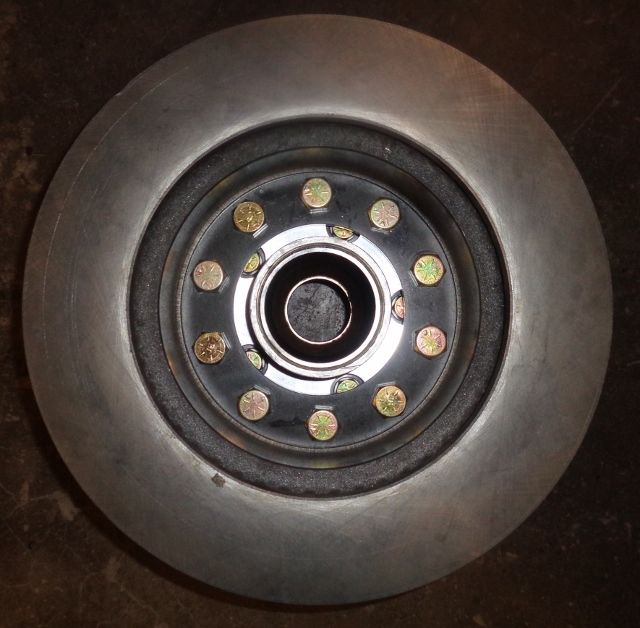
This is a 1/4" thick plate that will be on the inside of the rotor when the rotor bolts are installed.
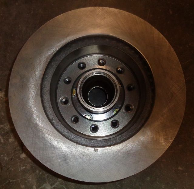
Here the rotor is bolted to the flange. This rotor was originally designed to be slipped over the wheel studs and the wheel holding it in place. So I machined the plate for the inside so the rotor is fully supported.
More photos.
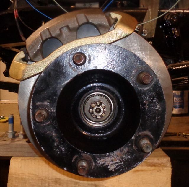
Here you can see the flange between the hub and rotor.
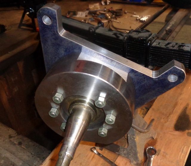
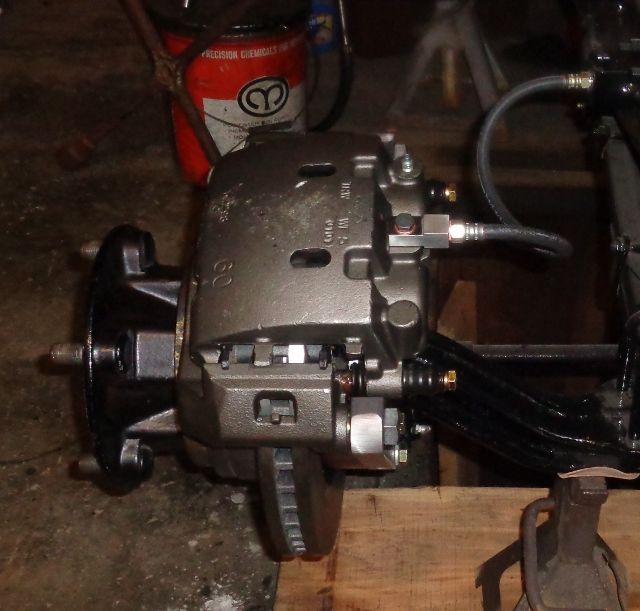
This is the caliper mounting bracket on the spindle. I added two more holes to the spindle brake mounting flange. Maybe not necessary, but I feel better with six bolts holding the caliper versus four.
Hub and rotor on the spindle.
This is showing the position of the caliper. It is in front of the axle, this is the drivers side.
The brake installed.
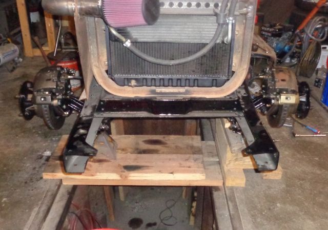
Both brakes installed. Please don't pay any attention to my messy shop.
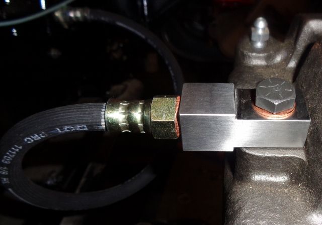
This is a banjo fitting that I machined to connect the original type hoses to the calipers. They are machined from 17-4 heat treated stainless steel.
Everything will have to be removed and I will paint the brackets. I will reinstall everything with grade 8 bolts properly torqued. Next will be the bracket for the new Master Cylinder and Booster, then I can plumb it all.
Thanks, Fred. You remembered correctly, 17-4 can be fun to machine. It can be especially hard on tools. I would still rather machine it than A2 though, I hate that stuff!
I ran an indicator on the rotor sides to see how much sideways runout that I have. The drivers side is at .004" but the passenger side is .014". I ran the indicator on the face of the flange that the rotor bolts to and it is between .001" and .0015". It looks like I will need to lightly face the rotor face that bolts to the mounting flange to true it to the rotor surface. Since these rotors are designed to clamp between the hub face and the wheel, they are faced true on the inside, so I need to machine the outside face true to the inside face. .004" runout on a 14.5" rotor may be acceptable, I will see if I can get it closer to .000".
Mark,
I'm in awe of your machining skills. This could solve a big problem for us big truck guys not having replacement front drums (plus added safety if we are using them as they were intended).
Now, all I need to do is figure out how to get a setup like this to work on Marmon Herrington's front closed knuckle axle...
Thanks Capt for the kind words. Are the front brakes on your M-H stock Ford brakes? Maybe the caliper bracket could be redesigned to fit your axle.
Mark
Might be doable. Below is the parts diagram for the F5 M-H conversion.
Part 5 is your knuckle and bearing cups that also have your steering arm connection. Problem is the outer bearing race is part of #5 and 7 (hub) when they slip together, and the oil seal is part of the hub. The trick would be adapting to the M-H hub to keep the bearing and oil seal intact, and keep the axle length the same with the splines.
Your design should work with some thinking and modification though... maybe next winter I'll figure it out.
Rezvani's Latest Post-Apocalyptic Monster Is a Ford F-150 Raptor Underneath
Slideshow: Called the Fortress, the 850-horsepower pickup combines Raptor underpinnings with military-inspired features, survival equipment, and a starting price of $285,000.