'49 F4 Disc Brake Conversion
#31
 03-09-2016, 07:56 PM


#32
03-09-2016, 09:41 PM
CaptPayne, It looks like, from the parts breakdown, that the brake drum on the M-H is closer to the wheel flange than on the stock Ford axle. I don't know with the size of the steering knuckle if the rotor would fit over it or not. If you decide to try this setup I can send you some dimensions and sketches to work from. I don't know of any M-H trucks near me that I could look at. I'll be happy to help any way that I can.
Mark
Mark
#34
03-09-2016, 09:55 PM
#35
03-16-2016, 05:22 PM
I chucked the rotors in the 4-jaw chuck of my lathe and faced the mounting surface true to the rotor brake pad surface. Now they both have .001"-.0015" sideways runout on the rotor brake pad surface. I think I can live with that. I need to face about 1/8" off of the caliper bracket mounting surface on the caliper bracket hub to move the bracket in toward the caliper. I now have a washer between the bracket and caliper, to properly position the caliper. I will be able to eliminate the washer once I face off the hub. Once that is done I can paint everything, pack the wheel bearings and reassemble the brakes and front hubs for the final time.
Mark
Mark
#36
03-24-2016, 05:21 PM
I assembled the hubs and rotors yesterday so I could get all the brake pieces painted and assembled for the final time. I realized last night that I had overtorqued all the bolts. I removed the bolts today on one rotor and noticed that the 1/4" plate that I machined to bolt the rotor to the adapter plate was deformed around all the holes. The rotor has all the holes countersunk fairly deeply on the side that the plate bolts to. The plate is deformed into the countersinks. I machined two new plates 1/2" thick from an alloy tube that I have, probably 4150 HT. When I get some new bolts I will reassemble them. Here are a couple of photos.
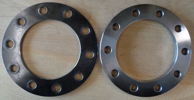
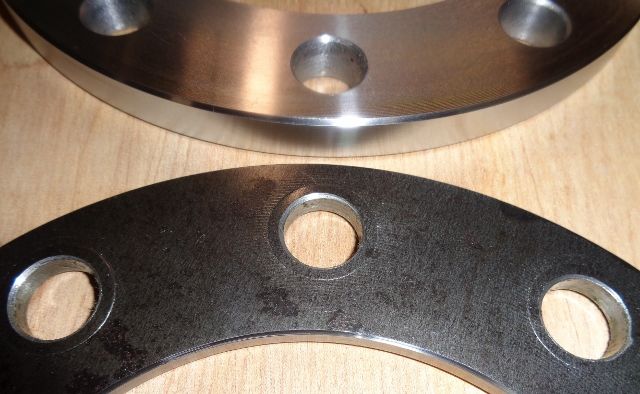
You can see in the photos the deformation around the holes. It may have been fine if I hadn't overtorqued the bolts.
I also made a pair of adapters so I could use '32-'37 hub caps.
I need to check with a buddy of mine and see if he can TIG the holes in this cap.
Thanks, Mark


You can see in the photos the deformation around the holes. It may have been fine if I hadn't overtorqued the bolts.

I also made a pair of adapters so I could use '32-'37 hub caps.


I need to check with a buddy of mine and see if he can TIG the holes in this cap.
Thanks, Mark

#38
03-24-2016, 07:35 PM
The outside diameter of the countersink in the rotor is probably a little over 3/4". The 5/8" lockwasher is about 7/8" o.d. There is a dimple on the other side of the plate around each bolt where the lockwasher was compressing the metal into the countersink. The chart I used for torque values was one I copied out of an issue of Antique Automobile from the 70's. The torque values for the 1/2-20 Grd 8 and 5/8-18 Grd 8 bolts I used, from that chart, are about 30 lbs higher than all the charts that I have found on the web. Add to that, I should have reduced the torque by about 15% as the threads had oil on them. So they were way overtorqued.
#39
03-24-2016, 08:14 PM
Ross,The rotors that I am using are front rotors on a 2005-2016 F450-F550 truck. In the original application they are slipped on over the wheel studs and held in place by the wheel. The back side of the rotor mounting surface is against the hub and the wheel would be on the front. The countersinks are on the side that faces the hub, I assume that there is a radius or shoulder on the stud at the hub and the countersink is for clearance. In my application, the front, or wheel side, of the rotor is against the hub and the back side with the countersinks is were the mounting bolts go thru into the hub adapter flange. I am using a plate under the bolts to mimic the clamping of the rotor between the hub and wheel in the original application. The deformation around the holes, I believe, is caused by a combination of too thin soft steel mounting plate and overtorquing the bolts. There probably would have been some deformation with the bolts properly torqued. With the lockwasher and countersink diameter being so close to the same size, the soft plate wasn't thick enough to give any support in the area around the bolts. The thicker plate machined from 4140-4150 H.T. should eliminate the deformation and even out the clamping force over the whole plate.
Sorry for the long post, I don't know if that made it any clearer or not.
Thank, Mark
Sorry for the long post, I don't know if that made it any clearer or not.
Thank, Mark
#40
03-24-2016, 09:45 PM
Fleet Owner
I'm just surprised that basically you punched a 1/4" thick steel plate. I would think the huge area of the plate would reduce the local pressure of the bolts after a small amount of deformation, but you're right, with a lockwasher about the same diameter as the countersink, it sure could happen. 1/4" seems so stout in most applications but it's elastic like any metal.
It's contrary to my intuition, but it's a "true fact" that lockwashers do nothing good. I wonder if you shouldn't consider using either a prevailing-torque nut with a hardened flat washer, or something like a flange nut? Do you have space for a larger diameter flat washer?
It's contrary to my intuition, but it's a "true fact" that lockwashers do nothing good. I wonder if you shouldn't consider using either a prevailing-torque nut with a hardened flat washer, or something like a flange nut? Do you have space for a larger diameter flat washer?
#41
03-25-2016, 09:34 AM
You are right, I guess we use lockwashers to make us feel better about an assembly but, they really don't do anything, at least not on hardened fasteners. "Proper" torque keeps the fastener tight. I do have hardened flat washers that I can use in place of the lockwashers, I will do that.
Thanks, Mark
Thanks, Mark
#42
04-04-2016, 06:37 PM
I disassembled and reassembled the hubs and rotors today with new grade 8 hex head cap screws. I used the new thicker rotor plates that I made. I used the torque specs from the Fastenal website for grade 8 with Loctite. I replaced all the lock washers with hardened flat washers and used 271 Loctite on all the fasteners. I checked the sideways runout on the rotors after assembly. The drivers side has almost .0015" runout at the outside edge, on a 14.53" dia rotor. The passenger side had almost .005", so I took it all apart again, cleaned and double checked for everything burrs and reassembled it. It now has about .0005" runout. Now I can pack the wheel bearings and paint all the brackets and reassemble for good. The front brakes will be finished. I can check another thing off my list . Slowly getting there.
. Slowly getting there.