When you click on links to various merchants on this site and make a purchase, this can result in this site earning a commission. Affiliate programs and affiliations include, but are not limited to, the eBay Partner Network.
Gauge Setup with Safety and overrides- Auber Instruments Digital
Figured it might be interesting to document this, in case others want to try it.
I've copyrighted the diagram to protect it from companies or other commercial entities. You are more than welcome to duplicate it for your own non-commercial purposes (and at your own risk) (I have no relationship with Auber Instruments)
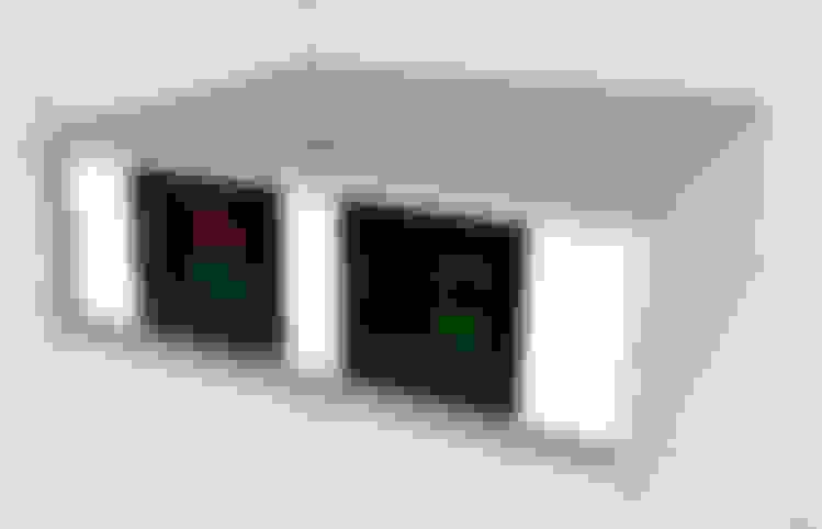
Red-Green is for EGT and BOOST.
Green-Green is for Transmission Temp and Fuel Pressure
You can easily set a high or low alarm for each display (each one is a dual unit). These alarms can trigger independent relays.
Here is the box I ordered.
I wanted the following features in a gauge setup.
1. Boost high alarm (user definable from the front panel)
2. EGT high alarm (user definable from the front panel)
3. Driver side and passenger side EGT sensors, selectable
4. Pre-filter and post-filter fuel pressure sensors, selectable
5. Ability to "shut down" the boost/EGT heat/whatever based upon alarm outputs
6. Ability to bypass any alarm/gauge reading individually from activating the shut down mode
7. Return to stock button
8. All-out, ignore all alarms mode button.
9. All controls in a nice, neat package that compliments the image of the truck (and the gadget-guy owner)
10. Glow plug operation feedback
11. Fuel bowl heater operation feedback
12. Power options: Off / On with Ignition / Always On
13. Buzzers, alarm LED, whatever as a visual indicator of a problem. Haven't decided what to do here yet. The gauges themselves have an alarm light, but might add something annoying
14. Lost track of this thought. Insert something brilliant here
Most importantly, I wanted "active gauges" that could actually react to certain thresholds- as I tell them to. Some of the ready-made gauges out there have alarm or relay triggers, too. I don't see why this couldn't interface with them, too
Here's what I've come up with on the sensor side, in a very basic Visio diagram. This doesn't show the other indicators and power options, I'll get into that a bit later.
As you can see, it uses 5 switches:
1 each for toggle between L/R EGT sensor and Pre/Post Fuel sensor
1 each for Alarm or Bypass mode of EGT and Boost
1 for Alarm / Stock / Max mode
It was important to me to have these up front as physical buttons rather than some software setting. It allows simple switching of modes without fiddling with the gauge menus and settings.
It uses ONE power connection, which will be source selectable for Off / ACC ON / Constant 12V
It will have a number of LEDs to visually show current mode. These will be dimmable and have Blackout mode (LEDs off).
The gauges will have Headlight Dim / Ambient Light Dim / Full On modes. They have inbuilt lighting levels, but I don't know that I can control the modes with switches. The above options would be simple input from headlights-on, or a dash optical, or break connection.
Glowplug indicator is LED to the GP relay as many have done already. The LED would live in this panel.
I'd do a similar LED for Fuel Bowl Heater. I've got the space and knowledge is power
I may look to see mounting options for my Hydra tune slot selector switch and USB connector on the rear...stay tuned
Wastegate:
I am planning to use a normally closed 12 air tube solenoid between the redline and the wastegate actuator.
CLOSED (no power) would be equivalent of disconnecting the redline and allowing max boost (with complimenting tune to disable defueling) by not opening the wastegate.
I will have to experiment by tightening the nut on the actuator arm, as many have done, to open at a maximum point as a "mechanical blow off valve" of sorts, Maybe 30 PSI?
OPEN (applying power to relay to energize solenoid) would effectively reattach the redline, which should cause the actuator to open the wastegate immediately (solenoid reaction time is about 2ms).
I will have to experiment here, too. Not sure how long it takes the actuator to move the wastegate- especially if it didn't have any pressure in it at all. Also gotta make sure a sudden burst of pressure doesn't damage the actuator
Anyone know?
User Selectable Boost and EGT
By setting different alarm levels, I can change my max Boost levels from inside the cab in under a minute. Not playing with nuts, springs, etc under the hood.
The same option for EGTs. I can set it higher or lower at will. No fluttering the pedal as some have had to do as they flirt with high EGTs
I can also return to stock and bypass it all OR ignore all alarms and go to MAX with the flick of a switch
Other Drivers
By selecting a mild tune and setting the switch to STOCK, it should be safe for anyone to drive, regardless of their knowledge of the gauge readings. (What's a high EGT? Is 1400 bad? )
I could also allow a bit more aggressive tune for towing or whatever and still have the alarms protect the truck, just in case things go south for whatever reason.
Any comments, suggestions, gotchas, ideas are all welcomed!
I am spitballing here but I am not sure the EGT reduction function will work as you desire.
If you limit boost by bypassing the turbine, but don't limit the amount of fuel injected your EGT will continue to climb.
NA engine EGT's can vary from the same to allot higher than forced induction and if you are in a chip position with enough fuel to get there I don't think reducing the boost will help reduce EGT's.
This will be easy enough to test once you get your wastegate
solenoid installed.
Ideally you would have the gauge defuel the chip position all the way down to stock.
I think we could get there with the Android tablet/gauge device and a Arduino/rPi.
I believe the xfinity gauge has this capability.
If you limit boost by bypassing the turbine, but don't limit the amount of fuel injected your EGT will continue to climb.
NA engine EGT's can vary from the same to allot higher than forced induction and if you are in a chip position with enough fuel to get there I don't think reducing the boost will help reduce EGT's.
Thank you for jumping in on this! People like you know much more about these trucks than I do. I can 'make things happen' with electronics, but often lack the knowledge of *what* needs to be done
Okay, I was attempting to mimic the stock function that limits the boost using the wastegate.
I hadn't considered fuel.
But wouldn't the computer cut back the fuel when it sees lower boost? It does on stock mode, right
I imagine it would likely have more fuel than necessary at that lower boost level, trying to nudge the engine to more power, which can cause EGTs to rise, but...
And I'm spitballing here, too, so please explain if I'm wrong...
The reduction of EGTs should be pretty significant as the WG opens, happening almost immediately, and it may want to rise a little due to 'extra' fuel, but it should still result in a fairly significant net decrease, right?
I have a Raspberry Pi, but what would it do differently? How would it signal a fuel decrease- especially since it is chipped and running a tune?
I could trigger basically anything with the relay output. I could even trigger a signal generator, conditioner, etc. Just don't know what else to trip besides the WG.
If we can't figure out the high boost= Lower EGTs by opening WG, I might just have to be satisfied with a user selectable max boost level opening the WG, which is still a benefit, just not as much.
Cody would answer this far better than I, but I've never known the tune to dial fuel back because of the lack of boost... unless a custom tune is set to do that. When boost isn't there, you have plenty of soot and heat, but the power is lacking because of the incomplete fuel burn.
In between other projects, such as brakes, tuning, and fuel pressure, I got a little time to play with this in Sketchup.
As separate layers and "removable" in the drawing to see internals, different angles or other details, I have top and bottom clamshells, each separate gauge (as group/object), a front and rear panel (face)
I have to work out mini-LEDs, switches, power (probably integrated circuit breaker), and wiring (ugh!)
First, here are a few screenshots to give you an idea what I have planned.
I'm looking for ideas and suggestions for the following.
1. Labels for switches and LEDs. This being a one-off, no silkscreening. Maybe some type of clear label with good adhesive?
2. Mini-LEDs. Don't want to have big holes or big bezels, but panel mount would be nice. Should be good for low voltage and full Alternator-charging voltages. The biggest fluctuations will be the GPR and Fuel Bowl Heater LEDs, which I intend to simply tap into the circuit, no circuit conditioning.
3. 2 Small selector switches. Thinking slide micros, but need a decent snap-in panel mount. Don't want to mess with screws or rivets if possible. Position 1 and Position 2. Off in middle is optional, but break before make is nice. Up to 3 amp to match the relay output would be plenty. Small and blends in with the panel face would be preferred.
4. 12v Power input. 12v-30v isolated is the spec on the gauges. I'd like something that isn't noisy or much draw/heat. Want to run both, but have separate switches. I can switch at the rear panel face with separate inputs, or one input and separate switches. Panel mount would be nice.
5. Wiring and connectors. Some sort of plugs/connectors for the sensors would be nice. Panel mount would be cool, but not required. The EGTs need to go directly to gauge, but everything else can be plugins, as long as they are secure and quality connectors.
I'm okay with assembly or solder connector types, but would prefer a quality and professional looking type of connectors. Don't want a bunch of crimp on spade connectors if I can help it.
Small connectors to attach to the terminals on the backs of the gauges. They are small, so ring, hook, etc are options. I don't have a crimper that small, maybe a suggestion?
In working out the actual wiring connections, and being unsure about the wastegate being the "answer" to dialing back the engine in the event of high EGTs, I simplified the diagram by stopping at the Alarm/Relay- in favor of working on a nice box and layout.
Here's the proposed dual EGT and Boost wiring diagram.
The Auber Ins site diagrams show the EGT ground line as (RED) that attaches to the PID's (-) terminal, so I maintained that. Won't know for sure until I actually test it, though. I found a programming error in one of these docs previously.
Can the Aubers alarm sounds be programmed/changed or are they hard coded? I'm kind of curious and looking to find a certain style alarm for over heats (high EGT) and use an air craft type set up as I'm used to that and don't want to learn two sets of alarm (trying to keep it simple to understand) for the same task
Can the Aubers alarm sounds be programmed/changed or are they hard coded? I'm kind of curious and looking to find a certain style alarm for over heats (high EGT) and use an air craft type set up as I'm used to that and don't want to learn two sets of alarm (trying to keep it simple to understand) for the same task
The gauge I have has an Alarm light on the gauge itself AND can drive up to 3amp light/buzzer/another relay/whatever.
My On/Off for the alarm is to disable whatever external thing I have triggering during an alarm. It will still light the AL warning light on the gauge face, though.
I admire the effort, but this seems like re-inventing the wheel here. I prefer to let the PCM control the wastegate by whatever sensors and algorithms Ford found to work best.
I'm no purist tho. Pulling and capping the red line will help boost and remove the PCM input. No problem with that.
The alarm just needs to trigger you. Then you lift your foot, take another gear, whatever.
If you want automatic control of EGTs you'll need glow plugs that double as type K thermocouples and an iPCM from Twilight Zone industries.
I've been looking at Allied as suggested earlier, too.
Finding DPDT slide switches that are very small and snap-in, and not board mounted, is proving challenging. I don't want big, bulky switches for the Left/Right EGT or Pre/Post Fuel Pressure.
Although I would take a DPDT 1-off-2 rocker switch Just have to find the real estate on the panel and/or small switches.
I am even considering push on/off for the alarms, though I don't care for that style in a control box (nor toggles), just to save space. I could move them to the side or even back if needed.
I have some 3mm LEDs coming shortly. That should save some space for the GP Left/Right indicators.
I think I'm dropping the fuel bowl heater LED. Apparently it is always on?
I'm looking at Molex connectors for the power and maybe non-EGT sensors.
EGT use special matched wiring, so likely to use a grommet for them. I'm thinking I will cut a little off the end of the longer sensor wires and use it from the DPDT selector switch to the gauge.
The switch will add some resistance, but if using a small capacity switch, resistance should be low and would certainly be even between left and right sides.
I may have to do some EGT accuracy checks after install. I can hook one side up through the switch and the other side directly to the other gauge as a test, then swap them if they seem to be too far off (to check L/R deltas)
Once my LEDs get here (smallest reasonable pigtails I could find), I may just go ahead and take a shot at placement of the front components, leaving the back panel off while I work out the details of the power entrance and stuff.
That way I can save the matching back panel if I need to cut a new front one. I can always fab and paint a new back panel. It would only have to be "close" in appearance, being in the back
I can certainly understand why many choose pre-made gauges and wiring, and round that accept a holesaw
But in my case, it's not just about saving $$, it's about doing something "special" Guess that's why we call ourselves "Enthusiasts"
I'm about to hit the road in 5 or so, but I know a place you might like but I can't remember off the top of my head. Give me a couple to do some searching.

 10-20-2015, 12:58 PM


 (I have no relationship with Auber Instruments)


 )
)