When you click on links to various merchants on this site and make a purchase, this can result in this site earning a commission. Affiliate programs and affiliations include, but are not limited to, the eBay Partner Network.
Hey,I am totally new to this forum and need help with my truck. I have a 2001 F650 7 speed with 7.3l powerstroke and I am pulling a 15,000 pound fifth wheel. It is very new to me and just doesn't seem to have the pulling power. It seems to struggle even on flat going 65mph and when it comes to hills it really slows down. Should I be looking into power chips? If so, which one? Is there something else that may be preventing the full power? Any suggestions would be really helpful.
I don't know much about these trucks when towing but let's get some baseline info.
Is the truck chipped or stock?
Do you have gauges? If yes, whats max boost?
If you have gauges, doesn't sound like it, what are your egt's?
I've learned that most of the time when people complain about lack of power, on these old trucks it's usually a boost leak. Inspect the firewall for any dark patches of soot and check the boots for oil seepage. You can even build a leak detector really cheap, just search for "7.3 boost leak tester"
I don't think it's a fuel pressure issue if you can tow 15k lbs. Boost numbers should be 15-18 stock and 22-25+ with red wastegate line plugged, IF you have no boost/exhaust leaks.
kb has you headed in the right direction at this point. That truck should have no problem handling that weight, especially with the 7 speed tranny. I would imagine the 650's have at least 4.30 gearing and huge brakes, so no issues there. There is something wrong either with fueling or boost/airflow. Chipping a truck that isn't performing like it should stock, is never a good idea. Let's get this thing worked out and running the way it should, then we can talk about performance upgrades. I am going to link to a buyers guide thread that may help you baseline this truck and see where the issue may be. If it passes all these "simple" tests, we may need to get a little more involved diagnostically speaking, but start here and then we can move forward.
Tools: Tools: Fuel Filter Cap Removal Tool / Flash Light / White Bond Paper / Stop or Wrist Watch w/Second Hand Sweep / DVOM / Vacuum Pressure Test Gauge Bar #014-00761 19-0002 / Fuel Port Adaptor and Pressure Gauge 0-160 PSIG
Step #1: Visual Engine/Chassis Inspection
Tools: Flash Light
Fuel Oil Coolant Electrical Hoses Leaks Check
Step #2 Check for:
a. Contaminates
b. Correct Grade and Viscosity
c. Miles/Hours on oil
d. Correct level.
Tools: White Bond paper
Step #3 Intake/Exhaust Restriction
Tools: Flash Light
a. Inspect air filter and ducts
b. exhaust system
c. Inspect exhaust back pressure device
Step #4 Intake Restriction
Tools: Vacuum Pressure Test Gauge Bar #014-00761 19-0002
a. Check filter minder or measure at WOT with magnehelic gauge.
b. Spec: Magnehelic-2"- 2.5" / Filter Minder / H20
Step #5 Perform KOEO on Demand Test
Tools: OBD-II On-Board Diagnostics, Phase 2 Vehicle Media Communications Unit (Scanner)
a. DTCs set during this test are current faults.
b. Note: IDM DTCs displayed here could be current or historical faults
Step # 6 Retrieve Continuous Trouble Codes
Tools: Bi-Directional Scan Tool
Note: IDM DTCs are cleared when codes are cleared
Step #7 KOEO Injector Electrical Self-Test
Tools: OBD-II On-Board Diagnostics, Phase 2 Vehicle Media Communications Unit (Scanner)
All injectors will momentarily buzz, then individual injectors will “Buzz” in sequence 1 through 8.
Step #8 Fuel Pressure Tests
Tools: Fuel Port Adaptor and Pressure Gauge 0-160 PSIG / DVOM
8a. Fuel Pressure at the right head
a. Verify that fuel is in the tank and the pump is being powered.
b. Measure fuel pressure at the front of right cylinder head Road Test- engine at full load condition Spec. Measurement / Head 0-160 PSI / WOT 45 PSIG min.
c. If fuel pressure fails low, go to step 8c.
d. If pressure is above min. spec, go to step 8b. 8b. Fuel Pressure at the left head
e. Measure fuel pressure at the front of right cylinder head Road Test- engine at full load condition Spec. Measurement / Head 0-160 PSI / WOT 45 PSIG min.
f. CAUTION: Secure hose away from turbo and exhaust
g. If fuel pressure is below min. spec, replace left check valve > If fuel pressure is above min. spec, Go to step 9.
8c. Electric Fuel Pump Pressure
a. Measure at fuel outlet from electric fuel pump: 45-80 PSIG > Road Test- engine at full load condition 45-80 PSIG
b. If fuel pressure fails low, go to step 8d.
c. If pressure is above min. spec, replace right check valve.
8d. Electric Fuel Pump Inlet Restriction
a. If fuel line is restricted above 6 Hg, check for: blockage between pump and fuel tank.
b. If fuel line is not restricted, inspect regulator valve condition and for debris, If OK replace pump
c. WOT under load Spec: > 42 psig
Step #9 Perform KOER on Demand Test
Step #10 Injection Control Pressure Tests
Tools: Bi-Directional Scan Tool / Stop or Wrist Watch w/Second Hand Sweep
b. Monitor ICP and RPM with Bi-Directional Scan Tool Hold engine speed at 3400 RPM for 3 minutes
c. Spec: ICP: 1800 PSI MAX @ 3,400 RPM
10b. Low Idle Stability (ICP Pressure)
a. Check at low idle, EOT above 180 F
b. Monitor ICP and RPM with the Bi-Directional Scan Tool 400 – 600 PSIG @ 670 RPM’s If engine RPM is unstable, disconnect the ICP sensor, If RPM is still unstable, change IPR and re-test.
c. If RPM smooth’s out, the ICP sensor is at fault. Note: ICP will default to 725 PSI when disconnected
Step #11 Crankcase Pressure Test
Tools: Vacuum Pressure Test Gauge Bar #014-00761 19-0002
a. Verify engine is at normal operating temp
b. Measure at oil fill with adapter and orifice tool P.N. 5631 & 014-00743 installed.
c. Block breather tube on left valve cover
d. Measure at WOT no load Spec < 3 H20
12. Cylinder Contribution Test
Tools: OBD-II On-Board Diagnostics, Phase 2 Vehicle Media Communications Unit (Scanner) / Stop or Wrist Watch w/Second Hand Sweep
a. Verify that EOT is above 70 F
b. Turn A/C and all accessories off
c. Select Cylinder Contribution from the test menu
d. NOTE: The test will run at idle speed for about 120 sec. and no engine change will be felt during the test
13. Exhaust Restriction
Tools: OBD-II On-Board Diagnostics, Phase 2 Vehicle Media Communications Unit (Scanner) / Stop or Wrist Watch w/Second Hand Sweep
a. Visually inspect exhaust system for damage
b. Verify EBP device is open at WOT in park or neutral
c. Monitor EBP with the Bi-Directional Scan Tool with the engine temperature at 170°F minimum at 3400 RPM
d. Spec: 34 PSI Max @ 3,400 RPM
14. Boost Pressure Test
Tools: OBD-II On-Board Diagnostics, Phase 2 Vehicle Media Communications Unit (Scanner) / Vacuum Pressure Test Gauge Bar #014-00761 19-0002
a. Verify that MAP hose is not damaged, plugged or pinched
b. Verify that intercooler hoses or intake are not leaking.
c. Verify that the green Wastegate hose is not plugged.
d. Monitor MGP (manifold gauge pressure) and RPM
e. Road Test - select appropriate gear to obtain desired engine speed and full load on engine (best accomplished climbing hill or truck fully loaded).
f. Spec: MGP 15 PSIG Min
15. Data List Monitoring Parameter:
V-PWR 10.5 VDC Minimum. (The CMP may fall out of the PCM circuit if vehicle voltage falls below 10.5v).
RPM 100 RPM Minimum (0 - CMP Suspect)
ICP 500 PSI or 3.4 MPAM Minimum the ICP should steadily climb during cranking. This indicates a healthy HPOP depending upon how high it climbs.
ICPv (KOEO) Spec 0.20v - 0.30v
FUEL PW: 1 MS - 6 MS (<1 / >6 IDM Suspect)
V-PWR - If indicating a low voltage condition, check battery voltage, charging system or power and ground circuits to the PCM.
DC% - Cranking NTE 20% / 65% is closed. (IPR Suspect)
2. RPM - Low RPM could be an indication of starting / charging system problems **
3. No RPM indicated with the engine cranking - could be CMP circuit fault, check for DTC’s.
4. ICP - A minimum of 500 PSI (3.4 mPa) is required before the injectors are enabled. No or low oil in the reservoir, system leakage, injector O-Rings, or faulty IPR could cause pressure loss.
Note: If no RPM signal is received, IPR duty cycle will default to 14%
5. FUEL PW - Even though a 1 to 6 mS FUEL PW is shown, it’s possible the IDM did not receive the signal due to a CI or FDCS circuit fault or internal IDM failure.
6. MAT: Manifold Air Temperature the PCM uses this signal to adjust fuel and timing.
7. VFD (Volume Fuel Desired)
8. MFD (Mass Fuel Desired)
9. ** If your scan tool supports, please export to a "*.cvs" file and post to Forum for review and chart formation. **
Known Good Sensor KOEO Voltage:
AP: 5 volts in, 0.5-0.7 volts at idle, 4.5 volts at WOT. PID: AP
BARO: 5 volts in, @4.6 volts/14.7 psi at sea level, decreasing as altitude increases.
CMP: high, 12 volts, low, 1.5 volts.
EBP: 5.0 volts in, 0.8-1.0 volts/14.7 psi
EOT: 5.0 volts in, 4.37 volts@32°F, 1.37volts@176°F, .96volts@205°F.
PID: EOT (degrees)
EPR: Exhaust Back Pressure Regulator, also EBP regulator Output: For quicker engine warm-up at cold temperatures. If the IAT is below 37°F (50°F some models) and the EOT is below 140°F (168° some models) the PCM sends a duty cycle signal to a solenoid which controls oil flow from the turbo pedestal. This causes a servo to close a valve at the turbo exhaust outlet. The PCM monitors the EBP input to determine if the EPR needs to be disabled to provide power for increased load, then reapplies the EPR as load demand decreases until EOT or IAT rises.
IAT: 5 volts in, 3.897volts@32°F, 3.09@68°F, 1.72@122°F.
ICP: 5 volts in, 1.0volt@580psi, and 3.22volts@2520psi.
EXBP 10-15psig w/ EBPV closed and not exceed 45psi at WOT Note: EXBP showing low (3-5psi) that barley rises with acceleration indicates bad sensor or plugged tube.
IDM: 110 volt signal to the injectors. Grounds each injector as fuel is required for that cylinder. Fuel Pulse width is increased to deliver more fuel. The IDM sends a feedback signal to the PCM for fault detection.
IVS: 0 volts at idle, 12 volts off idle. PID: IVS (off/on)
IPR: Coil OHMS = 10.2 - 10.6
MAT: Manifold Air Temperature the PCM uses this signal to adjust fuel and timing.
VFD (Volume Fuel Desired)
MFD (Mass Fuel Desired)
Get an OBD 2 bluetooth dongle and get Torque Pro off the Play Store and you can monitor boost, icp, Ipr, injector PW, oil temp, tranny temp and a bunch of other things.
I wouldn't chip it yet... you have base issues with the engine and you can make things worse. The Custom tunes link in my signature has more info on this.
Gauges plus Torque Pro, AE, or some other scan tool/gauge are a huge help with our aging fleet.




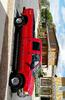



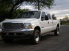


 I dont know how to rotate it? I rotated it on my phone and still came out like that?