


3G alternator upgrade


Thread Starter
|
New User
Joined: Jul 2009
Posts: 5
Likes: 0
3G alternator upgrade
about to do the 3G upgrade and I am seeing many conflicting posts on using resistors in line with the green/red wire. I understand if you have an idiot light a resistor should already be in parallel with the light (in case the light burns out there is still path for current to flow and excite the alt). I've seen people add resistors in addition in line, and some say they didn't add one and its been working great for years. My understanding is if you have an idiot light you already have a resistor in the circuit causing a small voltage drop (and redundancy if the bulb burns out) If you don't have the idiot light you should add a resistor to provide the same voltage drop?
I have the three wire regulator (no idiot light, no "I" terminal) as shown in the top photo. Powermaster says add a 50 ohm resistor and connect to the "S" terminal. The other diagram says add a 560 ohm resistor. What's right, does it matter?
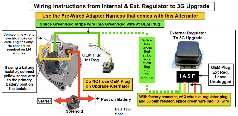
Courtesy of Powermaster Performance
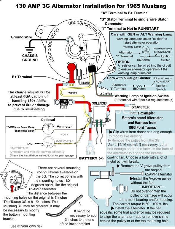
Sorry don't know the original source of this, seen it many places
I have the three wire regulator (no idiot light, no "I" terminal) as shown in the top photo. Powermaster says add a 50 ohm resistor and connect to the "S" terminal. The other diagram says add a 560 ohm resistor. What's right, does it matter?

Courtesy of Powermaster Performance

Sorry don't know the original source of this, seen it many places

Logistics Pro

Joined: Aug 2003
Posts: 4,701
Likes: 6
I have a 79 with gauges and here's what I did:
The green wire off the "2" plug goes straight to the connector on the 3g-wire-to-wire and nothing else.
On the "3" plug, I just looped and re-soldered the two heavy wires, as all three of them are just spliced in the harness anyway.
I ran lawn mower cables to the 175A fuse and to the solenoid.
Finally, just throw away the ext regulator.
The green wire off the "2" plug goes straight to the connector on the 3g-wire-to-wire and nothing else.
On the "3" plug, I just looped and re-soldered the two heavy wires, as all three of them are just spliced in the harness anyway.
I ran lawn mower cables to the 175A fuse and to the solenoid.
Finally, just throw away the ext regulator.
Senior User
Joined: Dec 2004
Posts: 469
Likes: 0
From: Bancroft, MI
I'm in the process of this upgrade. The only issue I have is I have no "I" wire coming out of the old regulator plug. So according to the diagram splice it into the white wire with a 50 ohm resistor right? It's on a 78 F150 body. Then I'm able to throw out all the remaining wiring?
about to do the 3G upgrade and I am seeing many conflicting posts on using resistors in line with the green/red wire. I understand if you have an idiot light a resistor should already be in parallel with the light (in case the light burns out there is still path for current to flow and excite the alt). I've seen people add resistors in addition in line, and some say they didn't add one and its been working great for years. My understanding is if you have an idiot light you already have a resistor in the circuit causing a small voltage drop (and redundancy if the bulb burns out) If you don't have the idiot light you should add a resistor to provide the same voltage drop?
I have the three wire regulator (no idiot light, no "I" terminal) as shown in the top photo. Powermaster says add a 50 ohm resistor and connect to the "S" terminal. The other diagram says add a 560 ohm resistor. What's right, does it matter?
Courtesy of Powermaster Performance
Sorry don't know the original source of this, seen it many places
I have the three wire regulator (no idiot light, no "I" terminal) as shown in the top photo. Powermaster says add a 50 ohm resistor and connect to the "S" terminal. The other diagram says add a 560 ohm resistor. What's right, does it matter?
Courtesy of Powermaster Performance
Sorry don't know the original source of this, seen it many places
Last edited by wooddyusa; Oct 31, 2016 at 01:59 AM. Reason: went back and read some more...
Senior User
Joined: Dec 2004
Posts: 469
Likes: 0
From: Bancroft, MI
Rookie maneuver yesterday. I was attempting to clock the alt and the case cracked. May be headed back over to the pick and pull tomorrow. I ended up splicing the green/red wire into the S-wire. I also needed to attach the large blk/ylw ignition wire to the hot side of the starter solenoid. Im getting there. I actually had the truck running once for a moment among battery connection/ground issues. More work on those tomorrow too.

Thread
Thread Starter
Forum
Replies
Last Post
kwajite02
Electrical Systems/Wiring
3
Feb 2, 2009 07:42 PM
firefighterF250
1980 - 1986 Bullnose F100, F150 & Larger F-Series Trucks
10
Dec 8, 2005 06:41 AM


