


250 I6 Build

Thread Starter
|
Senior User
Joined: Dec 2012
Posts: 160
Likes: 0
Well I just looked and I haven't posted anything on here since September so here we go.
I got the head back from the machine shop last month but really didn't get anything done other than having about 1/4" of the mount machined off. Come to find out I laid the adapter out wrong and the way I had it, it wouldn't work. I think I ordered the wrong carb anyways because when I sit it on the manifold, the fuel inlet hits the valve cover. So I thought of spacing it up but then hood clearance becomes an issue. So after staring at the mess I just put my self into, I figured out a way to make it all work. I got a piece of 3/16 plate for the brackets and have way more than I'll need so I am going to build a plenum and cut out the intake and weld it in. I test this theory with the old 144 head I had and worked out fine. This way the throttle shaft will be running through the axis of the crank instead of parallel with it. This will let the stock throttle cable to be reused and route over the valve cover and the fuel inlet will be in a better location.
So on to the next mess, the header. Yeah I knew I was shooting in the dark when I ordered the Mustang header but eh what ever. Well the collector is hitting the frame so that don't work. So I cut the flange off the header where it bolts to the head and I'm going to cut the collector off and bolt a plate from the mounting bolt set at the right spot, bolt the collector to the plate and just cut and re weld the tubes back on. I just got my prep materials and gas lens in for the TIG welder so that won't be a problem.
I went and got the sheet metal for the oil pan so I can get that done when the engine comes out and goes on the stand. Then it's on the table for header and serpentine drive.
I just got the engine bolted in today, got the transmission mount and cross member fabbed up and bolted in and got the driveshaft mocked up and ready to take it to the shaft shop. I can't trust myself to take measurements for the shaft and this way I know it's right and it fits. Got to mark the bell housing for the clutch fork and get a bushing machined for the pilot, fab up the bracket for the slave cylinder and get the clutch line remolded (haven't figured this one out yet) and get the fuel lines routed. Then I have to get the rad support brackets cut off and rewelded and the brackets trimmed back. Got to move the whole thing moved forward about 1 1/2". Then I will pull the engine and transmission and put the finishing touches on everything, then it's off to the machine shop. Feeling pretty good now. Can't wait to hear this thing run not to mention getting hitched to the trailer and pulling for the first time.
Haven't took any pictures yet but will be sure to take pictures of all the stuff I've had to build and modify to make this work which hasn't been a whole lot. Might start something if others can see how it all came together.
Cranky Old Guy
Joined: Mar 2008
Posts: 3,562
Likes: 6
From: Raphine, Virginia
Yes, pictures would be nice. You may get some ideas you haven't thought of. Not sure of your issue with oil pan, but I had a picture of a 144/170/200 oil pan spliced to the 250ci pan to make it rear sump. Keep plugging away and it will come together.
Thread Starter
|
Senior User
Joined: Dec 2012
Posts: 160
Likes: 0
The center sump pan hits the cross member where the I-beams connect. I know you can put a body lift to raise the tunnel and get the engine to slide in a little more, but goal is to keep it as original as possible and as cheap as possible. I dropped the pan about 2" and the small bellhousing and transmission fit well. The pump is about an 1/8" off the bottom. I actually had a 144 pan that I was going to use to do that, got excited and jacked it all up. Thought **** on this and went and bought a sheet of 16 ga. I need some sheet metal around the shop and will need some pieces for the rad. support so just spent 30.00 on a 4x5 sheet. Then I thought, if I'm going to build this pan, might build a high capacity pan. Probably not a bad idea since it will be a tow truck that gets run hard on the hottest days of the year.
Next project is the plenum which I won't lie, makes me somewhat nervous. Welding cast iron to steel is always a gamble as to whether or not it cracks.
Next project is the plenum which I won't lie, makes me somewhat nervous. Welding cast iron to steel is always a gamble as to whether or not it cracks.
Thread Starter
|
Senior User
Joined: Dec 2012
Posts: 160
Likes: 0
Well started on the serpentine drive and had to shut it down. The harmonic balancer hits the oil pan and timing cover so I dropped it off today at the machine shop to have it thinned. It's coming together none the less, but it should be worth the effort, never seen one of the smaller 6 cylinders with serpentine drive.
Thread Starter
|
Senior User
Joined: Dec 2012
Posts: 160
Likes: 0
Just finished the intake tonight, hope it didn't crack. Didn't hear the dreaded bell toll of popping cast so hopefully all is well. Cleaned the weld area real good and brushed with a wire brush and didn't see anything so fingers crossed. Finally got to see the Weber sit on the head for the first time tonight. Got to say that feel like a major achievement in itself. I also got lucky yesterday because I boogered the header up real good. Not that I couldn't fix it but it would have cost me a lot of money buying new bends. I went by to ask about getting some exhaust tube bent up and the guy told me to pull a box off a shelf. Sat it on the ground and it was the remains of a U-Fab header kit. "It ain't got no instructions so your on your own" is what he told me but has plenty of pieces left and even had 2 collectors be it for a V8 but I can work with it. I'm basically going to build a block hugger and merge 1,2 & 5,6 together at the collector and pull 3 & 4 over the other and each run in their own hole.
Also I'm in the process of uploading pics of the intake from knocking the flux off the rods to mounting the carb. I figured I would just start a new thread with pics and captions describing what and why I'm doing things. This thread is 4 pages deep, probably better to start new. Going to try and finish the header this weekend so there will be pics of that going up as well. Then the oil pan and pick up. I'll go ahead and snap some of the mounts and cross member too. Then it's off to finish the serpentine belt.
Also I'm in the process of uploading pics of the intake from knocking the flux off the rods to mounting the carb. I figured I would just start a new thread with pics and captions describing what and why I'm doing things. This thread is 4 pages deep, probably better to start new. Going to try and finish the header this weekend so there will be pics of that going up as well. Then the oil pan and pick up. I'll go ahead and snap some of the mounts and cross member too. Then it's off to finish the serpentine belt.
Thread Starter
|
Senior User
Joined: Dec 2012
Posts: 160
Likes: 0
Well as everything I touch nothing ever works out like I originally plan and it always take a tangent in the other direction. I guess I bought the wrong configuration on the carb so an adapter wouldn't work because the throttle wouldn't hook up right and the other way my fuel inlet with inside the valve cover so is just made the darn thing work. Probably won't see another one set up like this
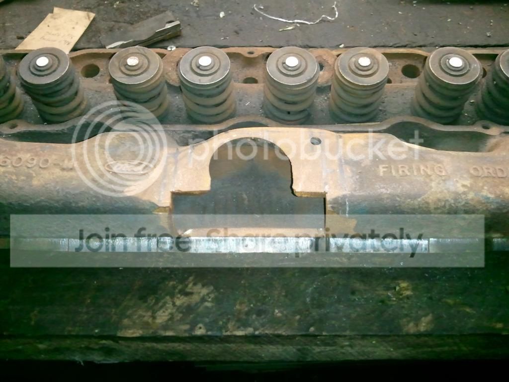
As promised, here are some pics of the 2 bbl. (or 2V as they're known in the 6 cyl. community) intake to mount the Weber 32/36 to.
Have a ton of pics from start to finish but figured I'd just post the basics, except the base being welded and carb installed but I'll put it up this weekend.
Here is what I started out with
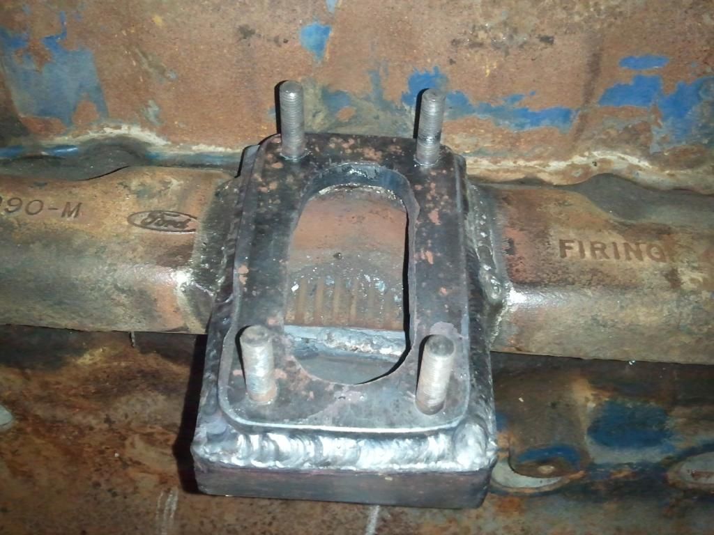
Here is the intake with the plenum welded on

Here is the base for the carb with a stud installed

The Weber setting on the base

Now that I have that done and nothing cracked and I don't need the TIG anymore, I can swap out the argon and get the gas for the MIG and start on the headers and serpentine. TIG is nice but MIG is so much easier and faster. In case anyone was wondering, I used NI-99 stick electrodes and just knocked the flux off and sanded them clean. No preheating or post heating but did peen, this is when I normally use my TIG, lot easier to get a single rod than a spool of wire and cheaper. Many more pics to come!
As promised, here are some pics of the 2 bbl. (or 2V as they're known in the 6 cyl. community) intake to mount the Weber 32/36 to.
Have a ton of pics from start to finish but figured I'd just post the basics, except the base being welded and carb installed but I'll put it up this weekend.
Here is what I started out with
Here is the intake with the plenum welded on
Here is the base for the carb with a stud installed
The Weber setting on the base
Now that I have that done and nothing cracked and I don't need the TIG anymore, I can swap out the argon and get the gas for the MIG and start on the headers and serpentine. TIG is nice but MIG is so much easier and faster. In case anyone was wondering, I used NI-99 stick electrodes and just knocked the flux off and sanded them clean. No preheating or post heating but did peen, this is when I normally use my TIG, lot easier to get a single rod than a spool of wire and cheaper. Many more pics to come!
FTE Stories
Ford Trucks for Ford Truck Enthusiasts

Rezvani's Latest Post-Apocalytic Monster Is a Ford F-150 Raptor Underneath
Verdad Gallardo
Top 10 Most Expensive Ford Trucks Ever Sold on Bring a Trailer
Joe Kucinski
2027 Ford Super Duty Buyer's Guide (Every Model, Engine, & Package)
Brett Foote
Top 10 Ford Truck Tragedies
Joe Kucinski
AEV FXL Super Duty - the Super Duty Raptor Ford Doesn't Make
Brett Foote
Lobo Vs Lobo: Proof the F-150 Lobo Should Be Even Lower!
Michael S. Palmer
Ford's 2001 Explorer Sportsman Concept Looks For a New Home
Verdad Gallardo
10 Best Ford Truck Engines We Miss the Most!
Joe Kucinski
2026 Shelby F-150 Off-Road: Better Than a Raptor R?
Brett Foote
Thread Starter
|
Senior User
Joined: Dec 2012
Posts: 160
Likes: 0
Thanks for the info, new to posting pics. So let me try this again.
Last piece
Installed

Serpentine drive that I am trying to fab up. The water pump pulley is a 3.0 serpentine/250 V-belt that I had to build. The harmonic balancer is from a 300 EFI engine, had 3/8" cut from the back. Alternator and A/C compressor is from the 3.0L and a GM power steering pump. Looks like crap now but it'll be cleaned up once I get it trimmed and the gussets get welded in.

Last piece
Installed
Serpentine drive that I am trying to fab up. The water pump pulley is a 3.0 serpentine/250 V-belt that I had to build. The harmonic balancer is from a 300 EFI engine, had 3/8" cut from the back. Alternator and A/C compressor is from the 3.0L and a GM power steering pump. Looks like crap now but it'll be cleaned up once I get it trimmed and the gussets get welded in.
Thread Starter
|
Senior User
Joined: Dec 2012
Posts: 160
Likes: 0
Not quite finished, still have 2 center tubes and the collector flange to weld on but just to give you an idea of what it will be. Cross between block hugger and manifold I guess, looks like a Jeep manifold to be honest. Just mocking up and tack welding, then I'll pull it apart clean it up and fit everything to "pull it tight" and MIG it all up. Let me know what ya think.

Cranky Old Guy
Joined: Mar 2008
Posts: 3,562
Likes: 6
From: Raphine, Virginia
It's coming together. Time will tell, but I think you will have fuel distribution issues with your carb flange orientation. These things flowed poorly at best, starving #1 and #6. Exhaust heat from #3 and #4 tubes "may" be an issue with your adapter sticking out over them. Not criticism, just comments. Good luck and keep updating progress.
Thread Starter
|
Senior User
Joined: Dec 2012
Posts: 160
Likes: 0
Yeah, I thought about that when I was designing it. I searched around online at different intake designs on inline sixes. I think it was a Ford or Jeep that I remember seeing an intake plenum like this. The Weber that I chose is the progressive 2bbl., the primary is located in the original position and works like the original 1bbl. The secondary is located over the plenum, I tried to limit the volume as much as possible though but who knows. I have a backup plan though. I can cut more out of the intake and turn the plenum long ways. I'm hoping it will work out though because the throttle cable will work out well. Not a whole lot can be done with an integrated intake, hopefully it won't flow much worse than stock. I don't know how it will work considering it will be a low rpm engine, probably never see above 3,000 rpms. I'm getting the header ceramic coated as soon as I get the timing and carb adjusted and I'm planning to make an aluminum heat shield that will sit about 3/16" off the header, hoping that will resolve any heat issues. I'll admit I don't have a clue what I'm doing, and this could be a complete waste of time, money and it not even run. If it is, all I can say I know how NOT to do it at that point ha ha  .
.
I really appreciate the responses, a different angle of view has saved alot of head ache in the past so please don't hesitate to pick it apart. I welcome all opinions and suggestions.
. I really appreciate the responses, a different angle of view has saved alot of head ache in the past so please don't hesitate to pick it apart. I welcome all opinions and suggestions.


