


Repairing Firewall Rust Damage
Thread Starter
|
Tuned

Joined: Mar 2013
Posts: 399
Likes: 3
From: Grand Rapids, MI
Well I've had some success, although not completely out of the woods yet. I ran a lead from the battery positive to the main power connector at the firewall (thus bypassing the engine compartment harness)... and power comes back! That seems to tell me there's a bad connection somewhere in that harness (the harness that starts at the firewall connections and routes behind the AC compressor then through the intake manifold, under the air box, and finally coming out at the solenoid area).
That connector has 7 wires: red/blue, black/yellow (ground), green/black, green/yellow, blue/black, orange (actually 2 orange wires together) & blue.
I'm going inside to rest on it for the night. Insights greatly appreciated, I'll try to tackle it tomorrow afternoon.
That connector has 7 wires: red/blue, black/yellow (ground), green/black, green/yellow, blue/black, orange (actually 2 orange wires together) & blue.
I'm going inside to rest on it for the night. Insights greatly appreciated, I'll try to tackle it tomorrow afternoon.
Logistics Pro

Joined: Jan 2002
Posts: 4,907
Likes: 39
From: suburban atlanta
The 1985 EVTM has the power lock relays connected to fusible link "P", BK/W at the starter relay. The lock relays are located on the radiator support drivers side, so in that year they did not travel over the engine as you indicate all else does.
That link is supposed to power the window motors also, but the EVTM shows the motors being powered from the fuse box... I believe they are powered from the fuse box, which might explain the door locks working. They don't go through the fuse box.
If the cigar lighter and horn work, they bypass the ignition switch, and that could be a commonality indicator towards the switch.
My ignition switch started to separate and be finicky about letting the engine run.
My book does not have a firewall connector shown. Fusible link at the starter relay spliced to wires that go directly to the ignition switch or the horn/cigar lighter as above,ADD:they go through the below mentioned fusibles.
The horn/cigar lighter wire is also spliced to feed the main light switch. If the horn works, the lights & lighter should work also. They bypass the ignition switch.
There is a splice in the harness, further past the fusible links at the starter relay, where the alternator output {BK/O} splices to a pair of fusible links O{range} {the ones that feed all your stuff}, back towards the battery {BK/O again}, and the ammeter shunt Y/LG{instrument panel ammeter indicator}.
If that splice were not coherent any more, you'd have your symptoms...
tom
hint: follow the large fat wire from the alternator to find some fusible links...
Last edited by tomw; May 10, 2014 at 08:08 AM. Reason: clarity
Thread Starter
|
Tuned
Joined: Mar 2013
Posts: 399
Likes: 3
From: Grand Rapids, MI
Thanks Tom. No action at the horn or cigarette lighter. Yes that black/white wire from the solenoid takes a different route (along the radiator support) than the rest (the one you said powers the door locks).
Still working through the problem. I was able to verify voltage after each fusible link near the solenoid (tested right where I'm pointing). Could those 2 relays just right of my hand have anything to do with the problem? Unfortunately I left my manuals and diagrams along with all my spare relays and other parts in Grand Rapids. Those 3 yellow wires disappear into the harness and I can't tell if they make a stop at those relays before heading to the driver side firewall.

I also verified there is NO voltage reaching the 2 fusible links (brown & red/green wires) at the driver side of the engine compartment just before the harness goes into the firewall.

That connector above is the one I ran direct power to last night which caused the hood light to come on when I fed voltage individually to the green and both blue wires.

This is the harness just before it passes through the intake manifold. The wires themselves appear good but there's a lot of crud buildup around them and I'm not sure what that's all about. Should I consider unwrapping the harness to investigate?

Still working through the problem. I was able to verify voltage after each fusible link near the solenoid (tested right where I'm pointing). Could those 2 relays just right of my hand have anything to do with the problem? Unfortunately I left my manuals and diagrams along with all my spare relays and other parts in Grand Rapids.
Those 3 yellow wires disappear into the harness and I can't tell if they make a stop at those relays before heading to the driver side firewall.
I also verified there is NO voltage reaching the 2 fusible links (brown & red/green wires) at the driver side of the engine compartment just before the harness goes into the firewall.

That connector above is the one I ran direct power to last night which caused the hood light to come on when I fed voltage individually to the green and both blue wires.

This is the harness just before it passes through the intake manifold. The wires themselves appear good but there's a lot of crud buildup around them and I'm not sure what that's all about. Should I consider unwrapping the harness to investigate?

Logistics Pro
Joined: Jan 2002
Posts: 4,907
Likes: 39
From: suburban atlanta
I might not have made clear what I was suggesting.
There is another pair of fusible links that are attached at the splice that has leads to the alternator output terminal AND back to the battery.
It is the 'working supply' splice in that if the alternator can power it, the juice flows from the alternator to the load, and if the alternator is not pumping juice, the flow will be from the battery, through the fusible links near the relay.
Follow the large wire from the alternator, black/orange {I put the EVTM back in the basement} I think and you'll find the splice. I think you have a problem right there as that is where all power, battery or alternator, comes from for the things powered off the fuse panel.
You definitely have a bad connection somewhere, and you may have flexed the loom in directions it hasn't seen in 30 years ... so moved something that is 'brittle' ... like a solder joint at a splice.
Follow the wire from the alternator out to where it joins the two orange (85 version) fusible link wires and the wires leading back to MORE fusible links at the relay. The alternator wire should run into about 3 other wires. My bet is the splice there is bad, or the fusible links are not connected well at their 'load' end.
tom
p.s. I did not go to photobucket with my old computer as it won't display their pics but for a second or so before blanking them out, but may later.
Thread Starter
|
Tuned
Joined: Mar 2013
Posts: 399
Likes: 3
From: Grand Rapids, MI
I might not have made clear what I was suggesting.
There is another pair of fusible links that are attached at the splice that has leads to the alternator output terminal AND back to the battery.
It is the 'working supply' splice in that if the alternator can power it, the juice flows from the alternator to the load, and if the alternator is not pumping juice, the flow will be from the battery, through the fusible links near the relay.
Follow the large wire from the alternator, black/orange {I put the EVTM back in the basement} I think and you'll find the splice. I think you have a problem right there as that is where all power, battery or alternator, comes from for the things powered off the fuse panel.
You definitely have a bad connection somewhere, and you may have flexed the loom in directions it hasn't seen in 30 years ... so moved something that is 'brittle' ... like a solder joint at a splice.
Follow the wire from the alternator out to where it joins the two orange (85 version) fusible link wires and the wires leading back to MORE fusible links at the relay. The alternator wire should run into about 3 other wires. My bet is the splice there is bad, or the fusible links are not connected well at their 'load' end.
tom


Logistics Pro
Joined: Jan 2002
Posts: 4,907
Likes: 39
From: suburban atlanta
You have a picture of two fusible links near the firewall. One end goes to the loads, the other to the source of power. They most likely should be hot at all times. If not, check going towards the battery, as I bet they are connected.
The two relays are ECM and fuel pump power, I think.
In looking at the last picture, it appears that the plug is not inserted all the way into the connector. I believe that is the conductor for power from the alternator(and for that matter, the battery). It looks loose. It should have power to the Y for sure, and possibly the BK/O(? cannot see). If the Y is hot, that is a good sign. The BK/O might only get hot with the alternator operating. I dunno.
The wiring diagram from the liberry shows a Y/W from the alternator that turns into a BK/OR at some point as it goes past the ammeter[there's a connection that leads off to one side of the ammeter]. It does NOT indicate physically where the junction is where the color changes.
Follow the wire that attaches to one side of the ammeter and it will be Y/W in one direction and BK/OR in the other, at some point, as they connect. That is the feed that goes to the rest of the vehicle. The Y/W going back to the alternator.
HOWEVER the diagram I have shows an additional BK/OR coming from the alternator directly that also ends up connecting to the Y/W=>BK/OR wire, after the ammeter. Two feeds. They join up and have, as does the 85, two more fusible links "D" and "E" [16ga black]that are feeding Y and BK/Or wires that continue on to the loads.
There is also a fusible link between the battery + terminal, [14Ga green] and the Y/W lead to the alternator. I believe that is the only power lead from the battery for all accessories.
I downloaded 4 jpg files borrowed from the library resource site that show the wiring. PM if you want.
tom
Thread Starter
|
Tuned
Joined: Mar 2013
Posts: 399
Likes: 3
From: Grand Rapids, MI
We got it Tom.
The black/orange lead (#291 in Ford's wiring diagram) that runs from the starter relay, along the radiator support, and to the driver side fusible links just before the main harness passes through the dash was badly melted. It's pictured here split apart from the harness and resting atop the radiator support.

14 gauge green fusible link to 12 gauge black/orange wire. Not sure why the wire is melted and the fusible link is fine. Maybe there was a black rubber fusible link between the two that melted and a PO spliced it out? The blue connector between the two doesn't look stock?

This picture is on the driver side where the black/orange wire (left) splits into 4 wires, 2 of which having 16A fusible links.

From the corrosion on the wire it has obviously been going on for a long time. As you mentioned earlier Tom it was most likely a case of the corrosion taking over while the truck sat for 6 months that caused the loss of power. At least that means I didn't create the problem while repairing the firewall.

I unwrapped the harness and verified no other wires had been burned then replaced that one with a larger 10 gauge wire and added a 25A fuse near the starter relay so I'd have an easy to check weak point in the future. Then I rewrapped the harness and put everything back together. It was not an easy harness to get to by any means.
The Bronco has had power ever since. It's actually here in Grand Rapids now so it's just passed a 150 mile test drive from Detroit.
Thread Starter
|
Tuned
Joined: Mar 2013
Posts: 399
Likes: 3
From: Grand Rapids, MI
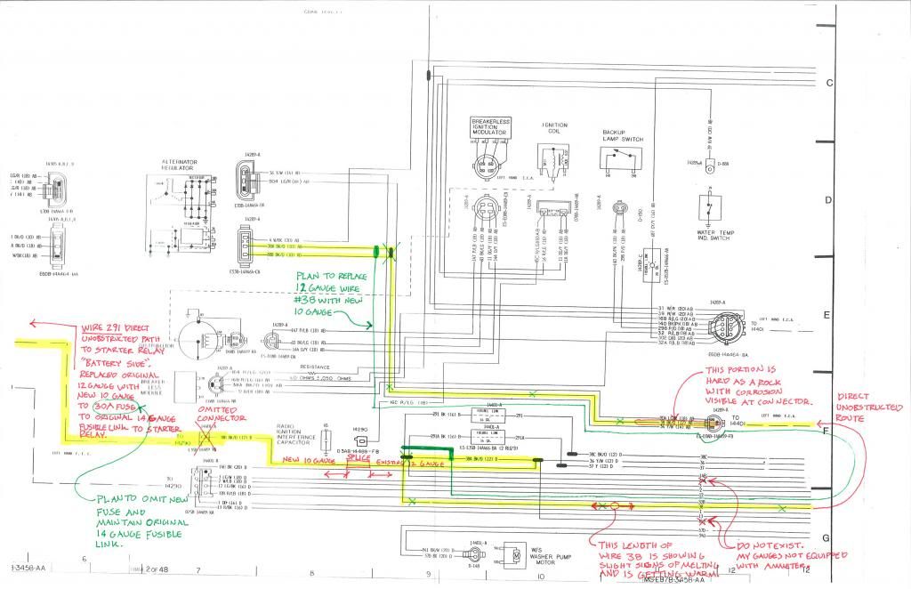
Sure enough that 25A fuse has popped so I put in a 30A (the highest allowable for the new 10 gauge wire). That's held up so far but I've been keeping an eye on the 4 original wires it feeds that don't have fusible links (36, 38, 654, & 655) and they're getting warmer than I like after long rides. 36 & 38 are both 12 gauge and go directly to the alternator. 654 & 655 are both 18 gauge and go directly to the instrument cluster ammeter. It is running great, I just don't feel comfortable with those wires getting so warm. Stay tuned.
FTE Stories
Ford Trucks for Ford Truck Enthusiasts

10 Things Every Truck Owner NEEDS (2026 Edition)
Michael S. Palmer
Rezvani's Latest Post-Apocalyptic Monster Is a Ford F-150 Raptor Underneath
Verdad Gallardo
Top 10 Most Expensive Ford Trucks Ever Sold on Bring a Trailer
Joe Kucinski
2027 Ford Super Duty Buyer's Guide (Every Model, Engine, & Package)
Brett Foote
Top 10 Ford Truck Tragedies
Joe Kucinski
AEV FXL Super Duty - the Super Duty Raptor Ford Doesn't Make
Brett Foote
Lobo Vs Lobo: Proof the F-150 Lobo Should Be Even Lower!
Michael S. Palmer
Ford's 2001 Explorer Sportsman Concept Looks For a New Home
Verdad Gallardo
10 Best Ford Truck Engines We Miss the Most!
Joe KucinskiThread Starter
|
Tuned
Joined: Mar 2013
Posts: 399
Likes: 3
From: Grand Rapids, MI
It's the black/orange wire (#38) that is showing slight melting. It takes a direct route from the alternator's output into wire #291 that I just replaced which goes directly back to the starter relay.
What I don't understand is why Ford designed for the alternator to push amperage through two 10 gauge wires that immediately splice into this one 12 gauge wire. The lonely 12 gauge just seems destined for failure. I'm tempted to replace it with a 10 gauge wire and call it a day but want to understand it better first.
What I don't understand is why Ford designed for the alternator to push amperage through two 10 gauge wires that immediately splice into this one 12 gauge wire. The lonely 12 gauge just seems destined for failure. I'm tempted to replace it with a 10 gauge wire and call it a day but want to understand it better first.
Logistics Pro
Joined: Jan 2002
Posts: 4,907
Likes: 39
From: suburban atlanta
Quote:
"That's held up so far but I've been keeping an eye on the 4 original wires it feeds that don't have fusible links (36, 38, 654, & 655) and they're getting warmer than I like after long rides. 36 & 38 are both 12 gauge and go directly to the alternator. 654 & 655 are both 18 gauge and go directly to the instrument cluster ammeter."
The two 18 gauge are for the 'shunt' that works the ammeter and carry none of the electrical power load. Instrumentation only.
The other two, 36 & 38 carry the power to the vehicle load, and the #291
BK/OR that goes across the radiator support to the starter relay. It is the battery charging lead, and also provides power to the rest of the fusible links on the starter relay 'battery' terminal {not starter side} which is hot at all times.
The power comes out the alternator on the two BK/OR leads that connect to #291, and also can go to the vehicle load via the fusbile links. When the alternator cannot produce enough power, the vehicle load will be taken up by battery, via #291.
In other words, the wire across the radiator support that had the melted insulation and corrosion carries power in two directions, depending on alternator output.
The same wire was likely overheated by a PO, and the fusible link by the starter relay got replaced, apparently after repairs were made.
From what I gather, you replaced the 14 gauge fusible link with the 25/30 amp fuse near the starter relay when you replaced the wire that goes across the radiator support.
I don't know the capacity that a 14 gauge fusible supports, but that is what you should be replacing, amperage wise. I'd think a slow-blow or even a circuit breaker would do fine. A fast acting fuse would not handle short bursts of load as well, and would be more prone to open.
If you can keep your hands on the 36/38 wires comfortably then they are likely not too hot. The fusible links are protecting them from carrying too much current.
The schematics I have shows a Y/WH output from the alternator and two more connectors with BK/OR wires that are joined together outside the alternator. The joined together BK/OR from the alternator junctions with the Y/WH, along with a R/OR and YEL/LT GRN. The latter two small gauge wires for the ammeter. The BK/OR leading to the starter relay also junctions with the previous mess. From that junction, there should be two fusible links that feed to the harness. One to a BK/OR and one to a YEL, each protected by a 16gauge fusible link.
In short, I would get a small circuit breaker or slow-blow fuse that matches the 14 gauge fusible, or wire in the fusible you have. After the fusible links at the junction mess, the BK/OR has a 20A fuse and the YEL has a 15A fuse further down the line towards the load. The JPG I have doesn't list fuse numbers nor wire numbers. As a guess, 20A on a 12ga is close to the limit, and that would mean it runs warmer than you like, but should be ok.
tom
Thread Starter
|
Tuned
Joined: Mar 2013
Posts: 399
Likes: 3
From: Grand Rapids, MI
I was wondering where you were the last few days. Hopefully enjoying your holiday break?
Well I definitely got my wish. The wiring is finally making sense to me and I'm able to follow the wiring diagrams. Your explanation above corresponds to what I found under the hood.
This wiring diagram hopefully shows a little clearer what I've been finding and the wires in question. Since wire 38 goes direct from the alternator to the starter relay I'd like to replace the remaining original 12 gauge portion of it with the larger 10 gauge, if nothing else for peace of mind. Any wires that splice into it have fusible links so I can't see the larger wire causing any issues. I also might remove the fuse I added near the starter relay and let the original 14 gauge link continue doing its work. I hadn't thought about surges potentially blowing my new fuse and maybe that's what was happening.
Found at http://www.bcae1.com/fuses.htm:
Suggested Fuse Sizes
Wire Gauge Recommended Maximum Fuse Size
00 awg 400 amps
0 awg 325 amps
1 awg 250 amps
2 awg 200 amps
4 awg 125 amps
6 awg 80 amps
8 awg 50 amps
10 awg 30 amps
12 awg 20 amps
14 awg 15 amps
16 awg 7.5 amps
Thanks for all your help Tom. I'll check in again after a few days to let you know how things are working.
This wiring diagram hopefully shows a little clearer what I've been finding and the wires in question. Since wire 38 goes direct from the alternator to the starter relay I'd like to replace the remaining original 12 gauge portion of it with the larger 10 gauge, if nothing else for peace of mind. Any wires that splice into it have fusible links so I can't see the larger wire causing any issues. I also might remove the fuse I added near the starter relay and let the original 14 gauge link continue doing its work. I hadn't thought about surges potentially blowing my new fuse and maybe that's what was happening.

Found at http://www.bcae1.com/fuses.htm:
Suggested Fuse Sizes
Wire Gauge Recommended Maximum Fuse Size
00 awg 400 amps
0 awg 325 amps
1 awg 250 amps
2 awg 200 amps
4 awg 125 amps
6 awg 80 amps
8 awg 50 amps
10 awg 30 amps
12 awg 20 amps
14 awg 15 amps
16 awg 7.5 amps
Thanks for all your help Tom. I'll check in again after a few days to let you know how things are working.


Thread
Thread Starter
Forum
Replies
Last Post
emeraldcoupe
1967 - 1972 F-100 & Larger F-Series Trucks
4
Oct 27, 2017 03:17 PM
Aarons54f100
1948 - 1956 F1, F100 & Larger F-Series Trucks
36
Jun 6, 2015 10:21 PM
427 fordman
1994.5 - 1997 7.3L Power Stroke Diesel
51
Jun 19, 2013 07:35 PM
Andrwm
Paint & Bodywork
7
Sep 8, 2009 05:22 PM