


Starting a 73-79 Wiring Tech Thread
Thread Starter
|
Logistics Pro

Joined: Aug 2003
Posts: 4,701
Likes: 6
Here is my wire splicing tool I made awhile back:

What I visioned and what came weren't exactly the same, but it works.
On weaker wires, the clip can pierce through the insulation once warmed up. I like the idea of the cloths pins, but unsure if it will hold tight enough for my liking.
Anywho, What I hope this thread delivers is a compiled list of connector pin-outs (or connector faces)
Example:

This will aid in repairs and modifications. Maybe also a list of connector manufactures, part #'s, and terminal types.
What I visioned and what came weren't exactly the same, but it works.
On weaker wires, the clip can pierce through the insulation once warmed up. I like the idea of the cloths pins, but unsure if it will hold tight enough for my liking.
Anywho, What I hope this thread delivers is a compiled list of connector pin-outs (or connector faces)
Example:
This will aid in repairs and modifications. Maybe also a list of connector manufactures, part #'s, and terminal types.
Maybe others can help with this info, but I am not that knowledgeable. Here's a website that does show some of the connectors that the factory used
Female Brass Open End Quick Connect Terminal - The Repair Connector Store
For aftermarket connectors, Waytech Wire and Delcity sell several different types.
This is another benefit of getting a junkyard harness. You can poach extra connectors.

Elder User

Joined: Jun 2012
Posts: 850
Likes: 0
From: Florida
details of options/subsystems and using the diagrams from my CDROM of the factory maint. man. to intergrate the Painless sys and 3G alt and headlight relay sys and other options
Ambitious, aren't I?!?

Lead Driver
Joined: May 2007
Posts: 6,993
Likes: 15
From: Costa Mesa, CA
Digging this thread! On a borrowed computer to get my FTE fix so don't have time to read it all yet. Subscribing for sure though and hope to add a bit when I get back in town & on my own computer.
Thread Starter
|
Logistics Pro
Joined: Aug 2003
Posts: 4,701
Likes: 6
I will. My plan is to use the old connecters and salvaged connecters along with NOS harnesses like MikeoOoOoO and ND are capable of finding for the
details of options/subsystems and using the diagrams from my CDROM of the factory maint. man. to intergrate the Painless sys and 3G alt and headlight relay sys and other options
Ambitious, aren't I?!?
details of options/subsystems and using the diagrams from my CDROM of the factory maint. man. to intergrate the Painless sys and 3G alt and headlight relay sys and other options
Ambitious, aren't I?!?
Unfortunately, over time most previous owners just hack stuff. It is nice to see people interest in doing quality repairs and upgrades.
Chasetruck: glad you find it useful. I am glad that others are covering more in depth stuff. My goal was to provide a useful thread that covers both basic and advanced wiring info for our trucks.
Lead Driver
Joined: May 2007
Posts: 6,993
Likes: 15
From: Costa Mesa, CA
Yeah it is nice to see some in depth, technical stuff for sure.
I'm currently going back in forth in my mind if I want to use the painless wiring, universal wiring setup I've had sitting around, or if I want to keep the majority of the stock wiring & add an up to date fuse block for adding new circuits like I did in my Alfa. Luckily my stock wiring isn't bad at all as far as hack job add-ons so either way I go shouldn't be too bad. I'm just wondering if it may be easier to use the painless from the beginning since it already has circuits for many of the modern conveniences I plan to add like power doors, windows, seats & seat heaters.
As others have said - this stuff isn't horrible if you take your time & use quality materials, connectors & tools. Do a nice job & it will last the life of the truck & be easy to add to in the future if needed.
Senior User
Joined: May 2012
Posts: 244
Likes: 1
Hey all. Digg the thread. I have experience turning wrench's but chasing wires, not so much. Skill level= dangerous. I do have a specific question, I'm thinking of doing the 3g alternator upgrade. I have a '78 F150 Custom, inline 6 300, my question is this is a1g to 3g correct? I have read a bunch if threads and feel confident that this is doable. Thanks Joe T
Posting Guru
Joined: Sep 2009
Posts: 1,159
Likes: 1
From: Suburbs of Chicago
Joe- yes its a 1G to 3G
Ted asked me to write some stuff about my underhood power distribution box.
Also, he mentioned my headlight harness mod which you can find here
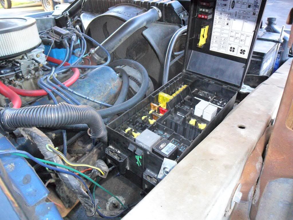
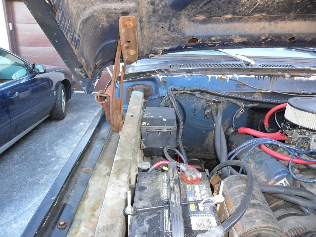
My underhood power distribution that I added is from a first generation Ford Focus. I added it for my upcoming MKVIII fan swap, and for my electric fuel pump, headlights, some in-cab accessories,etc.
Here's mine set up in the engine bay, those two really big relays at the bottom will be for the fan, the little 2 are for my headlights and fuel pump.
And this is what they look like stock with most of their slots full when you pull em from the yard.
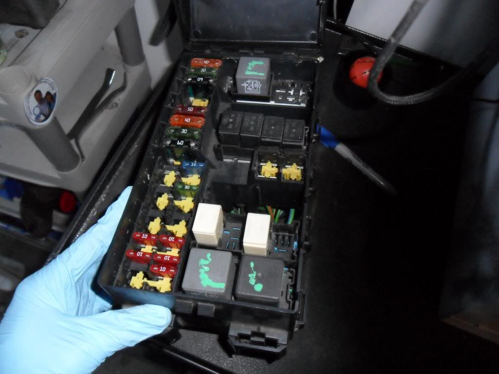
Spots for maxifuses, ato fuses, 5 pin, 2 high-amp 4 pin and 1 high amp 4 pin as well as 2 diodes if you're running some computer controlled stuff.
This row of 4 5-pin relays is pretty useful, I've harvested em from a few Focii, the stacks you see are for grinnergetter's seat project (nightmare).
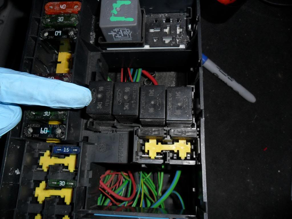
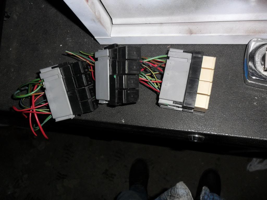
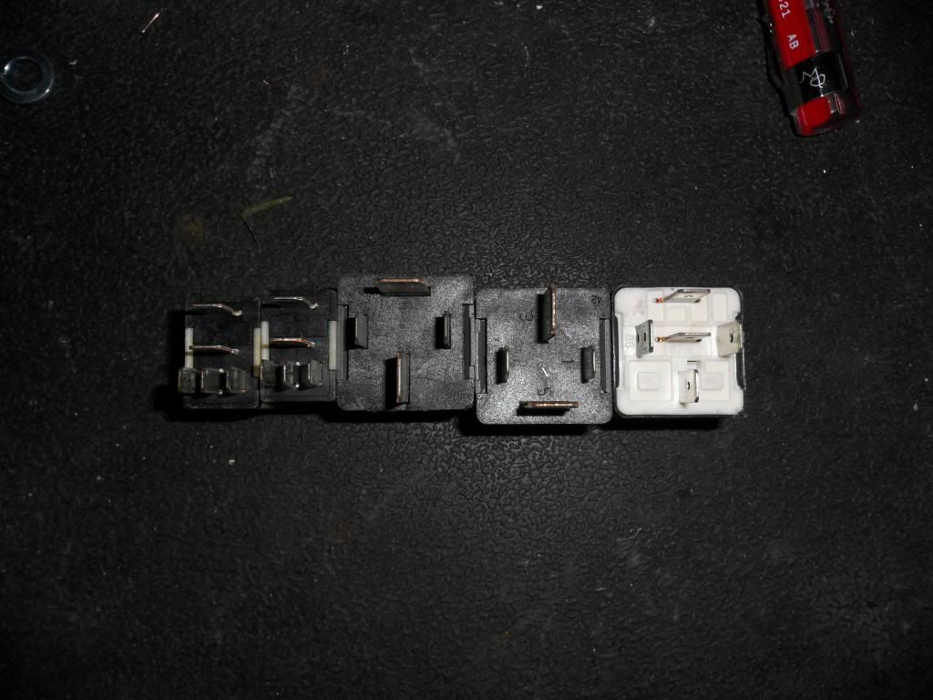
These are relays that it will come with. The 5 pins are very common, you can find them in Ford's and GM's in the yard. The 4 pin ones have MASSIVE 30/87 terminals, and I've only really seen them on Fords. These can handle A LOT of amperage, ideal for the MKVIII fan swap. The big 5 pin is good for the fan on low speed, leaving you 1 extra huge 4 pin. There are quite a few little 5-pins, so don't worry.
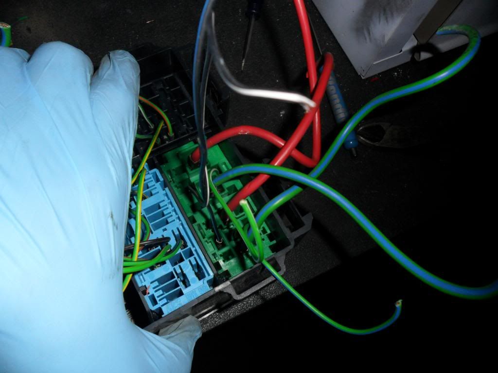
So pop the bottom cover off the box, this is what you'll see. It's intimidating, I agree. Unfortunately, because so much is PCM controlled, you really can't use much of it in its current state. So it actually gets easier, and you'll see why.
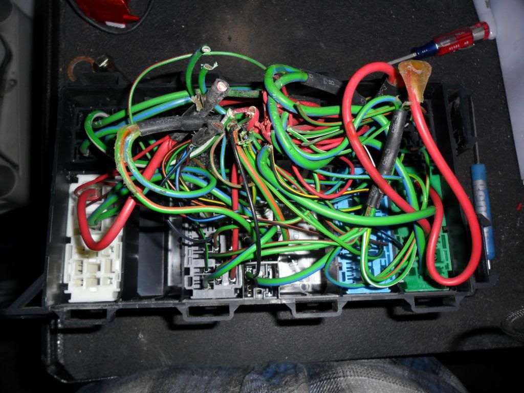
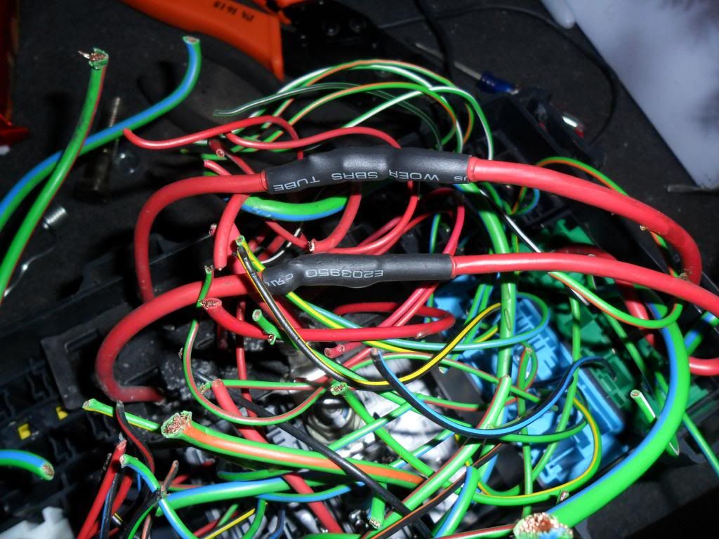
Wherever you see the factory shrink/hotglue splices, cut the splices out but make sure you leave enough to work with. DO NOT cut any of the wires completley out yet. It will make it easier to work with. You'll now see this on one side
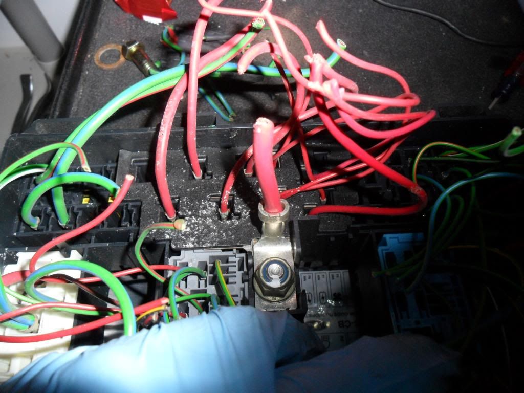
Anything under that plastic cover (you see how some of the bottoms are covered by plastic underneath the red wires?) gets its power from that big lug right in the middle. Connect that to your B+ with some sort of circuit protection.
I'd suggest the two wires all the way on the left that are red that go into that cover you use for your MKVIII fan if you're going that route. The one on the left most for high speed, the one that is one slot over but kiddie corner for your fan low speed. Grinnergetter, you have no choice, this is your box that I'm doing this how-to on
Those two will connect to these two relay terminals. Use the red wires as your hot, and the light green/blue as your outputs from the relay. The one more towards the middle of the box is your high speed, the one in the corner there is for your low speed. That's how the relays are set up in terms of handling amperage, so I'd follow that but its up to you.
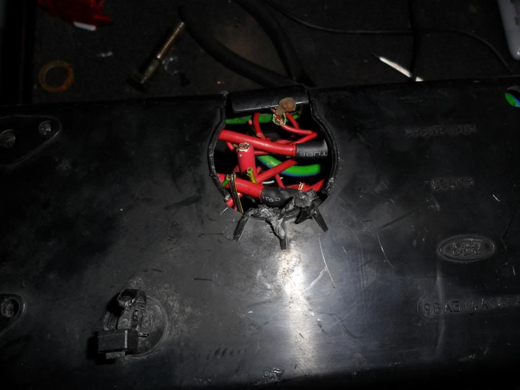
Now connect the wires that I told you to use for high/low, and label the cover accordingly. It should look like this, but the picture is just a little deceiving because it looks like I have the wires switched around but if you look closely you can see the high-speed feed curling around.
Connect a wire to your outputs, and your hot lug, snap the cover back on and you're home trees, boys.
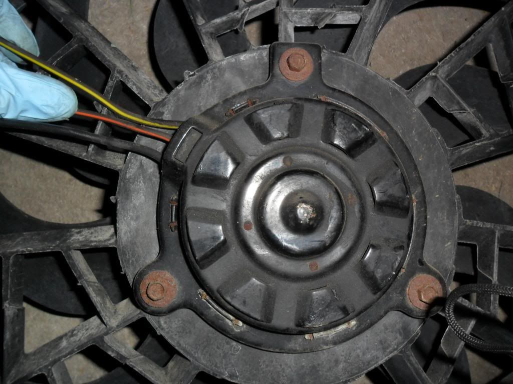
I'm also working on seeing if I can hack the 3 speed motor out of this Taurus fan (bottom) into this 2 speed MKVIII fan body (top). Stay tuned. Motor dimensions are the same, but the drive flange is different. Grinner, thats your alternator too.
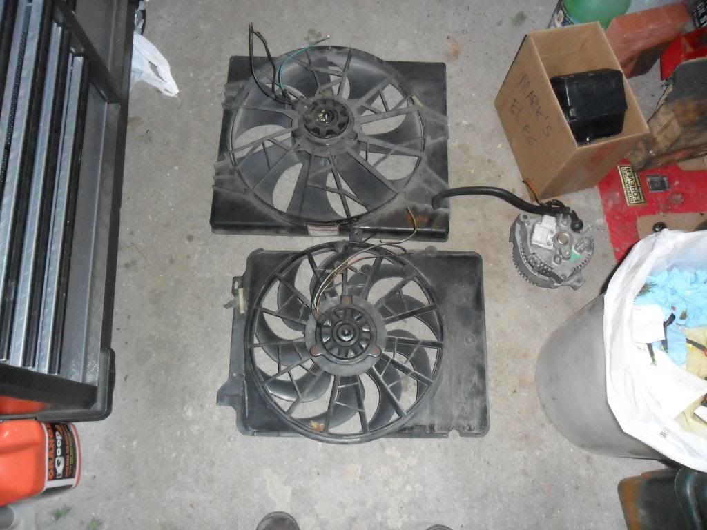
MKVIII motor:
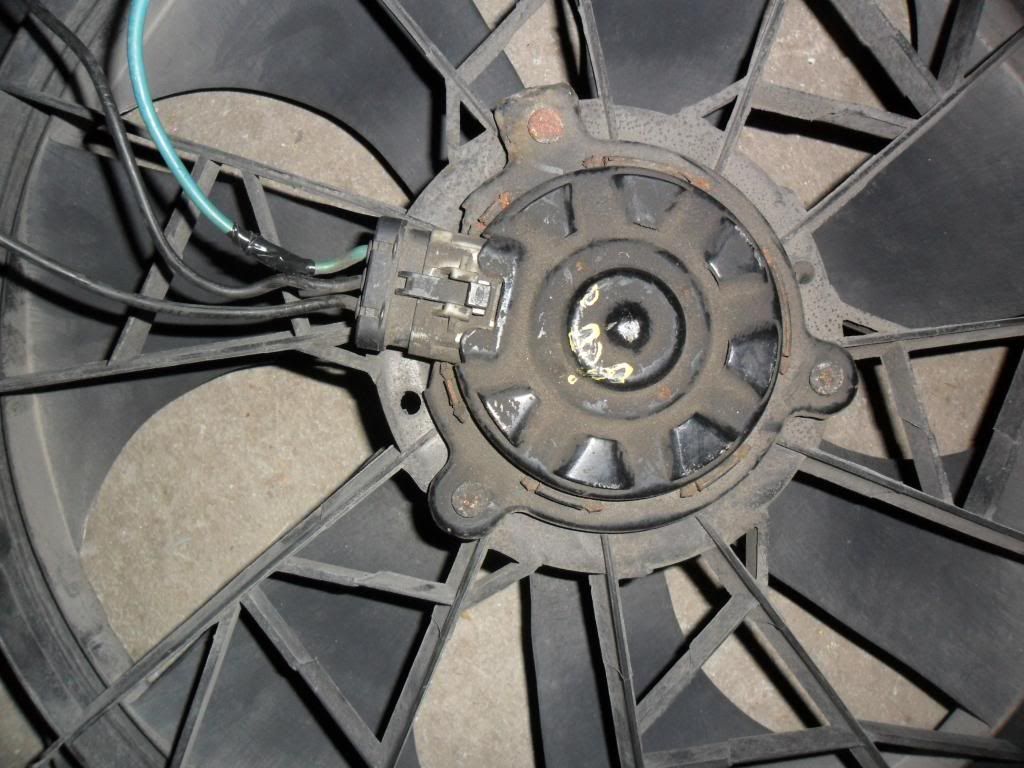
Taurus motor:
Ted asked me to write some stuff about my underhood power distribution box.
Also, he mentioned my headlight harness mod which you can find here
My underhood power distribution that I added is from a first generation Ford Focus. I added it for my upcoming MKVIII fan swap, and for my electric fuel pump, headlights, some in-cab accessories,etc.
Here's mine set up in the engine bay, those two really big relays at the bottom will be for the fan, the little 2 are for my headlights and fuel pump.
And this is what they look like stock with most of their slots full when you pull em from the yard.
Spots for maxifuses, ato fuses, 5 pin, 2 high-amp 4 pin and 1 high amp 4 pin as well as 2 diodes if you're running some computer controlled stuff.
This row of 4 5-pin relays is pretty useful, I've harvested em from a few Focii, the stacks you see are for grinnergetter's seat project (nightmare).
These are relays that it will come with. The 5 pins are very common, you can find them in Ford's and GM's in the yard. The 4 pin ones have MASSIVE 30/87 terminals, and I've only really seen them on Fords. These can handle A LOT of amperage, ideal for the MKVIII fan swap. The big 5 pin is good for the fan on low speed, leaving you 1 extra huge 4 pin. There are quite a few little 5-pins, so don't worry.
So pop the bottom cover off the box, this is what you'll see. It's intimidating, I agree. Unfortunately, because so much is PCM controlled, you really can't use much of it in its current state. So it actually gets easier, and you'll see why.
Wherever you see the factory shrink/hotglue splices, cut the splices out but make sure you leave enough to work with. DO NOT cut any of the wires completley out yet. It will make it easier to work with. You'll now see this on one side
Anything under that plastic cover (you see how some of the bottoms are covered by plastic underneath the red wires?) gets its power from that big lug right in the middle. Connect that to your B+ with some sort of circuit protection.
I'd suggest the two wires all the way on the left that are red that go into that cover you use for your MKVIII fan if you're going that route. The one on the left most for high speed, the one that is one slot over but kiddie corner for your fan low speed. Grinnergetter, you have no choice, this is your box that I'm doing this how-to on
Those two will connect to these two relay terminals. Use the red wires as your hot, and the light green/blue as your outputs from the relay. The one more towards the middle of the box is your high speed, the one in the corner there is for your low speed. That's how the relays are set up in terms of handling amperage, so I'd follow that but its up to you.
Now connect the wires that I told you to use for high/low, and label the cover accordingly. It should look like this, but the picture is just a little deceiving because it looks like I have the wires switched around but if you look closely you can see the high-speed feed curling around.
Connect a wire to your outputs, and your hot lug, snap the cover back on and you're home trees, boys.
I'm also working on seeing if I can hack the 3 speed motor out of this Taurus fan (bottom) into this 2 speed MKVIII fan body (top). Stay tuned. Motor dimensions are the same, but the drive flange is different. Grinner, thats your alternator too.
MKVIII motor:
Taurus motor:
Senior User
Joined: May 2012
Posts: 244
Likes: 1
I have read your head light upgrade before and grabbed a fuse block similar to yours. Thought it was a good idea. Borrowed my buddies soldering gun. About ready to start my 3g upgrade. But my other question is the Mark VIII fan upgrade. I've been reading threads and haven't conclusive proof that a light weight fan and clutch are not just as effective and easier. So my question is died the electric fan take a load off the engine, as in do you get a couple more horse power. As I have said previously I have a inline six, and could use any more hpi could get. Thanks
FTE Stories
Ford Trucks for Ford Truck Enthusiasts

10 Things Every Truck Owner NEEDS (2026 Edition)
Michael S. Palmer
Rezvani's Latest Post-Apocalyptic Monster Is a Ford F-150 Raptor Underneath
Verdad Gallardo
Top 10 Most Expensive Ford Trucks Ever Sold on Bring a Trailer
Joe Kucinski
2027 Ford Super Duty Buyer's Guide (Every Model, Engine, & Package)
Brett Foote
Top 10 Ford Truck Tragedies
Joe Kucinski
AEV FXL Super Duty - the Super Duty Raptor Ford Doesn't Make
Brett Foote
Lobo Vs Lobo: Proof the F-150 Lobo Should Be Even Lower!
Michael S. Palmer
Ford's 2001 Explorer Sportsman Concept Looks For a New Home
Verdad Gallardo
10 Best Ford Truck Engines We Miss the Most!
Joe KucinskiPosting Guru
Joined: Sep 2009
Posts: 1,159
Likes: 1
From: Suburbs of Chicago
Joe- Consider this. 1 hp = 746 watts. Lets say your mechanical fan only drew 1 hp, which is very conservative.
An electric fan runs on 12v, and draws maybe 30A on high. 12v * 30A = 360 watts, which is half a horsepower roughly.
Now the charging system may not be 100% efficient, but even if your fan only drew 1hp, an electric fan would be more efficient.
The other thing with an electric fan is you can control when you want it on and off.
Since the 2 speed MKVIII fan's are like the holy grail, I might be considering going with the 2 speed taurus fan pictured above. It depends on what you're going to be using the truck for.
Posting Guru
Joined: Dec 2009
Posts: 2,134
Likes: 1
From: Mississippi
Hmm, could it have been that tri-motor that was flying around Dade Co back in the late '80s? I remember reading about it being in the area and actually saw it flying around the Redlands, think it flew into Homestead General airport.
Hotshot


Joined: Apr 2009
Posts: 14,333
Likes: 247
From: Stanley, VA

 Nope, I lived in Dade County for 35 years (I was born there). Had a C150 based at Tamiami and flew in and out of Homestead quite a few times, flew down to the Keys a lot too.
Made the second worst landing I ever made at Homestead
 , the worst I ever made was in Venice (Fla not Italy).
I flew the Tri-motor when it was in Lakeland, after I moved up here to central Fla.
End of hijack, back to the thread.
Cargo Master
Joined: May 2010
Posts: 3,365
Likes: 12
From: NW Indiana
Wycked: alternator looks nice...thanks.
The kid(wycked) started to try to tell me how this was going to work on my driver seat and I said ..."uhm yeah that sounds like it will work....now when ya coming over".
The kid(wycked) started to try to tell me how this was going to work on my driver seat and I said ..."uhm yeah that sounds like it will work....now when ya coming over".
Posting Guru
Joined: Jul 2009
Posts: 1,536
Likes: 0
From: Schweinfurt Germany
Its all good my man it is common in my new line of work as a diesel mechanic a lot of times the only way CAT will warranty anything is either replace the whole things or do it like that.
It isn't hard but if you don't pay attention you could end up with a two and a half foot long stick of solder you would be surprised just how much they can suck up through the insulation
It isn't hard but if you don't pay attention you could end up with a two and a half foot long stick of solder you would be surprised just how much they can suck up through the insulation