When you click on links to various merchants on this site and make a purchase, this can result in this site earning a commission. Affiliate programs and affiliations include, but are not limited to, the eBay Partner Network.
85*c isn't high enough for an automotive application. Digikey or Mouser will have all the caps you are looking for.
The ECU resides inside the cab, so that 85C rating will be good. 63V caps will do just fine.
Even 25V rating will work, now if your are using 16V rating capacitors, then the failure rate increases as 14.2V charging system will sometimes spike over 18V(regulator switching transients,relay kick back, motor EMF) and any capacitor rated at 16V will be damaged over time.
I have seen this in the past 22 years of electronics repair, use components that are rated just above levels of the circuit. Years later after the warranty is up, that "weak link" component will fail.
Its called:" planed obsolescense "
I purchased a batch of replacement capacitors several months back but have yet to do any repairs yet. I definitely spec'd the 105C parts and upped the 16V parts to 25V, leaving the other one at 63V.
I had planned to package up my spares and sell them but want to actually do a couple repairs first.
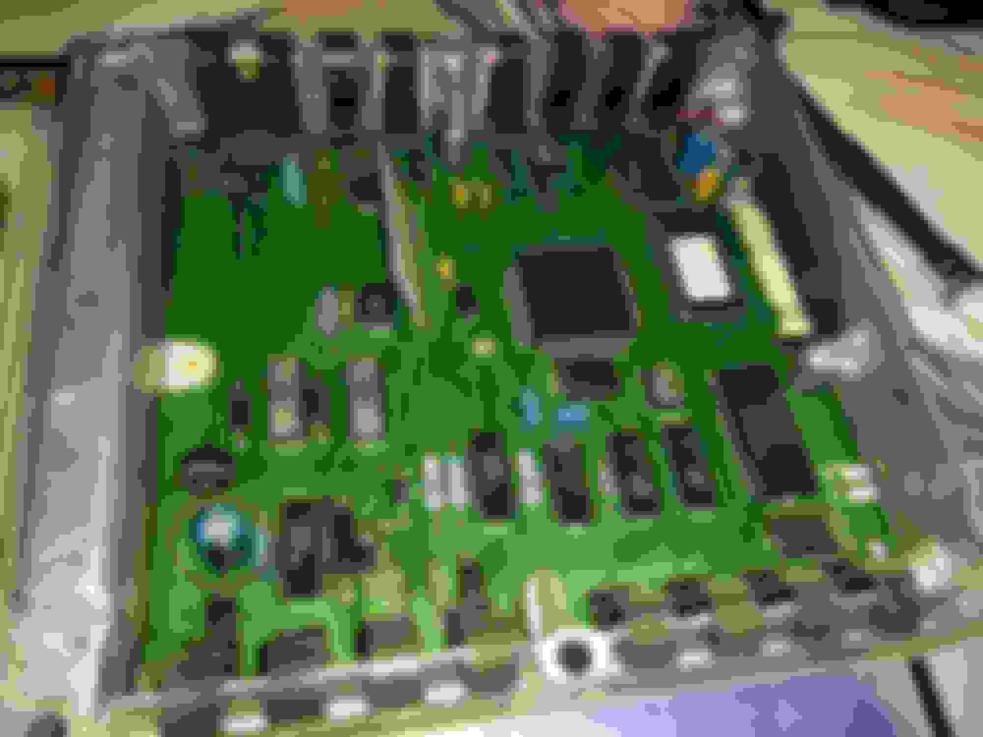
I'm getting ready to do my cap replacement (mostly mentally), I took the ECM out and opened it to find what looks like a very new ECM. Apart from that, I don't seem to be able to find the 3rd capacitor (maybe mine just doesn't have that one????), check out these pics:
I've read that too, but wanted to confirm mine was one of those, I guess that's better for me. I'm about to begin working on it, just researching some more and building some confidence.
Well alright had the chance to pull the ECM and do the preventive maintenance.
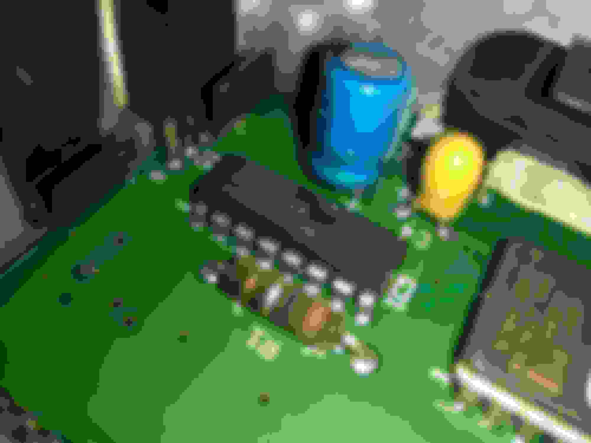
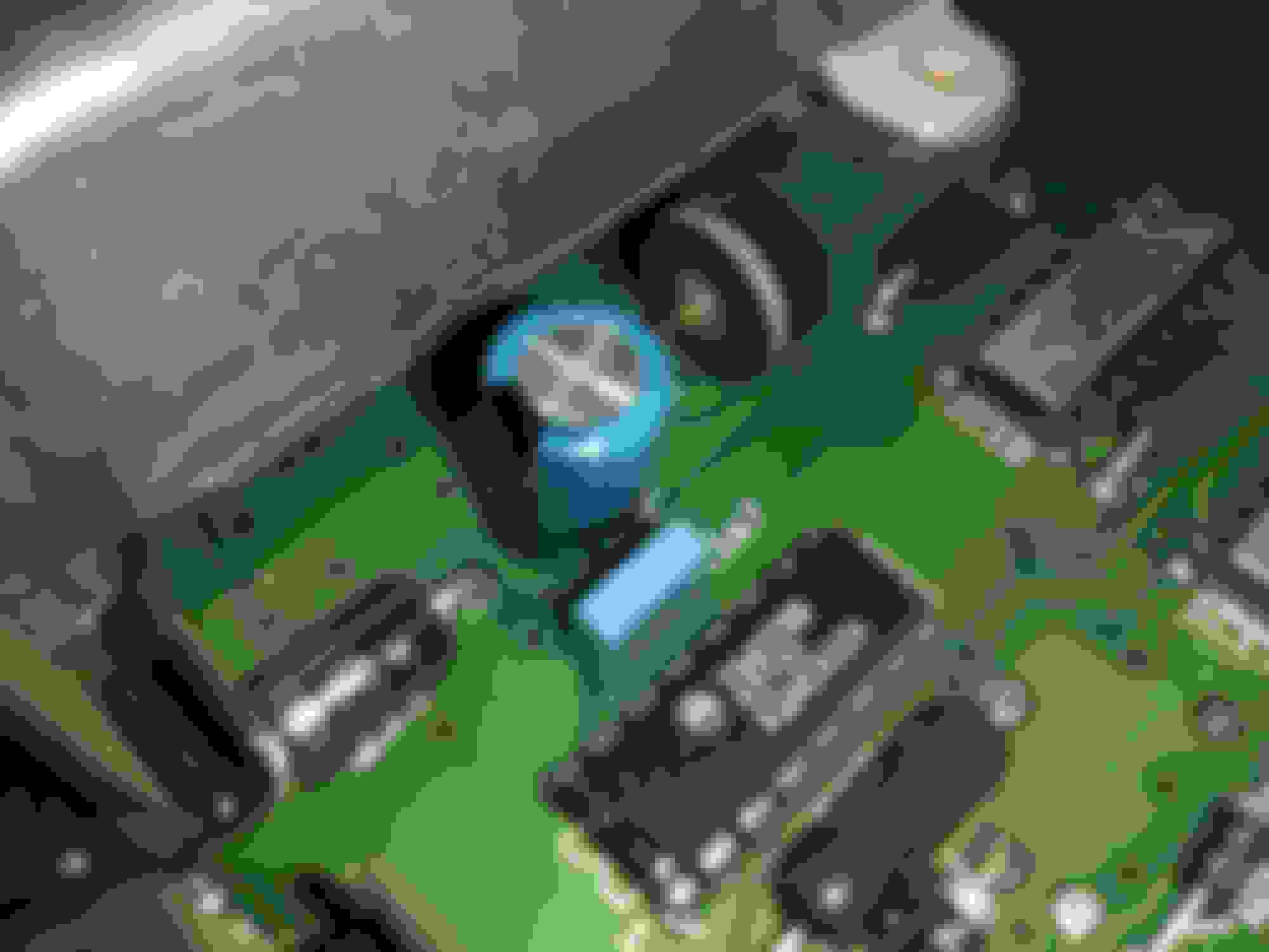
Mine is not like most I guess because I have only two capacitors. One 47uf 10v and one 3.3uf 63v.
I don't have the 3.3uf 63v capacitor as I ordered what most were using in theirs.
But I did replace the 47uf 10v as I had replacement ones.
I looked and my 47uf cap had yellowish coloring on the negative leg. So that one is replaced.
I gave digikey a call tonight and ordered the 3.3uf caps they should be here on Friday, $27 shipping 🤔 for a .63 order.😖 But I need to have it done by Monday so I have to pay out the a$$ for shipping.
But back to the ECM, I added some pictures so others will know what to look for. Lower right cap was removed. Going to clean the board with contact cleaner.
It has a lot of dust in it. Old vs new. My phone couldn't focus, but the negative leg has discoloration. Installed. Just in case it matters the ECM #.
....I don't have the 3.3uf 63v capacitor as I ordered what most were using in theirs....
The voltage rating of capacitors isn't that important. You wouldn't want t go lower than the original rating, but the only problem with going higher is if the replacement piece just doesn't physically fit. A lot of people go with higher voltage caps to gain some safety margin.
However it is critical to get capacitors with the right capacitance (the "uf" rating).
It's analogous to resistors, where you need the correct resistance (ohms) and enough current rating (amps), but getting a resistor rated for more amps isn't a problem.
It seems these two Caps are in the +5v Ref circuit, and supply the REf v for the TPS, EVP & MAP devices on ECA Pin 26.
Could a malfunction in one of these sensors cause the Caps to fail?
Short to ground? Ect.
In a word, no. However, an external short from 12 volt battery to Vref+5 would not be good.
The circuit is a Linear Regulator. A brief look through the circuit... Q1 is the series-pass transistor, and dissipates the most power, it is heatsink mounted. Q2, a Darlington pair, acts with R2 as a current limiter. If total output current increases to a point where the voltage drop across R2 approaches the base-emitter turn-on point of Q2 (~1.4v), then Q2 starts to turn ON, robbing base current from Q1. 1.4v/.51 ohms=1.96 amps, so that is approx. the max current draw.
IC6 is the reference.
If that was all there was to the circuit, a short of +5 to ground would overtemp Q1, as the dissipation would be ~14v-0v=14v*1.96A=~28 watts. So a protective current foldback circuit is implemented via a tap on the output via R7 & R4, and Q3. As the resistance to ground at the 5 volt output is lowered, first, current will be limited to approx. 2 Amps. If the resistance to ground decreases far enough, at that point Q3 starts to turn OFF, removing base current from Q1, so Q1 will start to reduce conduction, the max current draw will reduce to less than 2 Amps. The closer the output is shorted to ground, the further current through Q1 folds back, limiting its overall dissipation. Output current will not equal zero in a direct to ground short, as some current needs to flow to avoid a "stuck in foldback" condition (a circuitry latchup).
There will be a pop quiz on this next week
Thanks for the schematic. I designed discrete linear and early switching regulators in the 1970's, coincidental to the much bigger projects I was working on. If it needed to be done, I had to do it, and quick.
I would guess there are. I got this one from another member, I can look him up. Were were helping a guy last year solve a Fuel & ECA issue, and he had a few schematics.
I would guess there are. I got this one from another member, I can look him up. Were were helping a guy last year solve a Fuel & ECA issue, and he had a few schematics.
Subford is his call sign.... on this Forum. I believe these are 1987/88 ECA schematics from what I remember.
Rezvani's Latest Post-Apocalyptic Monster Is a Ford F-150 Raptor Underneath
Slideshow: Called the Fortress, the 850-horsepower pickup combines Raptor underpinnings with military-inspired features, survival equipment, and a starting price of $285,000.