When you click on links to various merchants on this site and make a purchase, this can result in this site earning a commission. Affiliate programs and affiliations include, but are not limited to, the eBay Partner Network.
Remote TFI Conversion using '92+ Sealed Bowl Distributor (4.9)
As most of us know, the factory went to a remote TFI configuration on the 4.9 starting in '92, and obviously that required a somewhat different distributor and harness. I know that electrically both setups work the same, so it's just a matter of getting things wired correctly.
There are lots of "generic" remote TFI conversion instructions out there, but all the ones I've seen are written towards converting a "regular" TFI-attached distributor to a remote setup. We have the advantage of being able to use a factory distributor and harness designed for a remote TFI, so that's what I would like to use - should be a cleaner and easier install.
Is there a write-up out there on doing this? So far I've come up empty.
Thanks, but I'm not really concerned with the parts - I've already got most, if not all of what I need. Just looking for some guidance from someone who's already walked down this path.
Might as well put some links in here. Here's one set of instructions for when you are going to continue using your existing disty.... Remote Mount TFI Ignition Module
Should be plug and play. If you have the harness, heatsink, TFI, and Dizzy, install it as a normal, remote TFI. You aren't really 'converting' anything over so much as changing it over. The new Dizzy and Harness should have everything you need to pop it right together (depending on what you have for remote harness); the only thing that changed was having 3 wires going from the PIP to the TFI and that's it (IIRC). Was there anything specific you were concerned with? And Good Luck!
-Mike
Also, its really the same as the other conversions you read about, but you get to use the stock dizzy connector instead of inventing a way to connect the PIP, and a stock harness, heatsink, and TFI on the other end.
Should be plug and play. If you have the harness, heatsink, TFI, and Dizzy, install it as a normal, remote TFI.
I don't want to replace the whole engine harness and IIRC the ignition sub-harness connection changed when the remote TFI went into production. So in short, I think it's not plug-n-play for that way I want to do it.
I think what I'll need to do is make a hybrid ignition sub-harness by piecing together portions of both. Just need to figure out the best way to do that.
Took a closer look at this just now and indeed the harnesses are way different between my '91 and the '93. Where the '91 has several quick connectors mounted to the driver's side splash shield, the '93 harness has one big 42-pin square connector.
It would seem that the best bet is going to be clipping out the quick connector and attached wiring that attaches to the '93 distributor and figuring out how to best patch that into my existing harness.
Upon further review, I'm now realizing that it will be easier to continue using the original distributor and make the modifications to use the remote TFI than it will be to modify the harness to use the '92+ distributor. I'd end up needing to make at least three additional cuts into the harness and run wires back and forth to use the later distributor. While that might gain me having a nice clean quick-connector coming out of the distributor, it would be at the expense of adding a bunch of wiring clutter and butt-splices elsewhere.
I guess now I'm realizing why nobody else has done this - it can be done, but the only way it makes practical sense is if you're replacing the entire harness (which is a pretty big project, cause you really need to replace EVERYTHING).
Nearly seven years later, I never did anything with regard to this, but I'm thinking about it again as I had a recent TFI (ICM) failure. The idea of using the '92+ distributor that is factory-setup for the remote TFI is more appealing to me than the DIY remote version. I'll have to re-investigate how much more cutting and splicing is required.
Any way, just wondering if anyone else has actually done this before me over the course of the past 7 years.
My plan is to get some donor harness clips at the junkyard from a '92 - '96 F-150 to build a sub-harness - I'd clip off both the distributor and ignition module quick-connectors with as much wire as possible.
Just wondering if there is any difference in the harness between the gray Vs black TFI trucks?
Also thinking that either a V8 or I-6 harness would essentially be the same for what I need, yes?
Best bet is to stay with a Push Start ignition harness. Anyone's guess if the V8 versus I6 harness is physically different due to the physical size difference in the engines.
Best bet is to stay with a Push Start ignition harness. Anyone's guess if the V8 versus I6 harness is physically different due to the physical size difference in the engines.
Yes, I'll stay with the gray TFI (push start) - i.e. upgrade from gray distributor mounted to gray remote mounted (pic below for those that don't understand). I won't be able to use the harness in it's entirety from the donor - I will build one from harness sections clipped off at the junkyard. Wire colors may match better if I get the donors from a gray remote mount, but other than that, it shouldn't matter. Same thing for the V8/I6 question now that I study it some more. I think my biggest requirement will be wires in good condition and longest run of wire so that I have the most flexibility in locating the TFI mount.
Adding this image/link which show good detail on the "Sealed-Bowl Distributor" used in '92 - '96. I didn't know until now that it had that name.
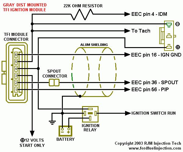
The early TFI system, which Ford calls the "Push Start" TFI system, uses a gray TFI module. Originally, the module was mounted on the distributor. In the late '80s, Ford began to relocate it away from the distributor on some vehicles to provide better protection from the effects of engine heat, but system operation remained the same. It uses a Hall effect pickup (stator) in the distributor, which generates a battery voltage, 50% duty cycle square wave, called the PIP signal, to the EEC and to the TFI module. The EEC processes this signal and sends out another battery voltage, 50% duty cycle square wave, called the SPOUT signal, to the TFI module. The SPOUT signal, short for SPark OUTput, is a digital signal generated by the EEC providing spark angle information to the ICM. The SPOUT signal on the push-start system controls only the firing of the coil. The falling edge of the SPOUT signal is ignored. The push-start system allows for increased dwell, or coil ON time, when starting the engine. The ICM on this system determines when to turn the coil ON based upon engine rpm information. The coil is then fired, or turned OFF, whenever a rising edge of a SPOUT signal is encountered. Ignition dwell with the Push Start (gray module) system is controlled by the TFI module alone, and increases with engine rpm. As long as the TFI module is receiving a SPOUT signal, it will fire the coil at the rising edge of that signal (except during engine cranking, when SPOUT is ignored) and the vehicle will run with the amount of timing advance commanded by the EEC. If the TFI module does not receive the SPOUT signal, it will fire the coil at the rising edge of the PIP signal, and the vehicle will run at base timing. This is true on all TFI systems. The start input on pin #4 of the Push-start TFI module is wired into the starter relay trigger circuit, and signals the TFI module that the engine is cranking. When the module sees battery voltage on this circuit, the SPOUT signal is ignored. The Ignition Diagnostic Monitor (IDM) signal on a Push Start TFI system comes from the coil negative circuit and is filtered through a 22k ohm resistor to pin #4 on the EEC. The EEC monitors this circuit to verify a coil firing for each PIP signal, and sets DTCs if it sees missing or erratic signals.
The internal circuitry of the ICM will have one of two possible arrangements: push-start (gray; ~'85-93), or computer controlled dwell (CCD) (black; '94-96)). NOTE THAT MOST AFTERMARKET MODULES ARE GRAY, regardless of type or year. If the ICM connector has a R/LB wire between the R/LG & Pk (pin #3), it's push-start (EZ-12A297-A or E7DF-12A297-A2A / Motorcraft DY-533); if the wire is Y/Bk, it's CCD (F1PZ-12A297-A or F1SF-12A297-C1A / Motorcraft DY-679)
Here's a good thread on someone who did exactly what I'm planning to do, except it was on a V8 Bronco. Process should be the same regardless. Pic of the relevant schematic.
Finally got this done yesterday - started right up on the first try!
Here's the schematic that I leaned on the most, as it's specifically designed for the "conversion" I did. There's a lot of different ways I could have done this, but ultimately I decided the least invasive approach was using just the junkyard clipped off harness pig-tail from the closed-bowl distributor. I left the original TFI connector in place on my truck, and it's now going to the remote TFI, mounted on a factory heatsink which is attached to the fender liner. Taking this approach, I had to clip three of the wires going to the TFI quick connector (PIP, 12V+ Run, IGN GND) and create a 3-way splice on each which connected the remote distributor. The other three wires remained as original, now going to the remote TFI.


 Z-12A297-A or E7DF-12A297-A2A / Motorcraft DY-533); if the wire is Y/Bk, it's CCD (F1PZ-12A297-A or F1SF-12A297-C1A / Motorcraft DY-679)