


Shake, Shake, Shake.....

Thread Starter
|
New User
Joined: Sep 2008
Posts: 42
Likes: 0
Shake, Shake, Shake.....
Has anyone ever had this happen to them? I am driving my F250 down the freeway today at 70 mph and go over a bridge and the truck starts shaking so bad that I honestly thought it was coming apart. I am not much of a mechanic but I have never had it do that. Is there something broke or bad or ... as you can tell, I am looking for any help. My college bound son thought we were in a transformer changing shapes. Any help or suggestions would be greatly appreciated.
Hotshot


Joined: Jul 2002
Posts: 18,358
Likes: 9,148
From: Sheridan / Gilchrist

Has anyone ever had this happen to them? I am driving my F250 down the freeway today at 70 mph and go over a bridge and the truck starts shaking so bad that I honestly thought it was coming apart. I am not much of a mechanic but I have never had it do that. Is there something broke or bad or ... as you can tell, I am looking for any help. My college bound son thought we were in a transformer changing shapes. Any help or suggestions would be greatly appreciated.
If it is doing it all the time now, I would start at the ball joints and or the universals and start working my way up the chain.
Thread Starter
|
New User
Joined: Sep 2008
Posts: 42
Likes: 0
Yes, quite a ride. It did it after the bridge until I slowed it down. No lift, no oversized tires, air pressure for the tires I have on it now are at 50 psi. This will tell you how much I know.... what is death wobble? Steering stablizer is stock. Thank you so much for the responses and help so far. That is why I enjoy this site so much.
MMNC (SS)(Ret)


Joined: Mar 2004
Posts: 11,606
Likes: 151
From: SE Georgia

Death wobble is when you hit a bump and your tires go nuts. Truck handles perfect all other times
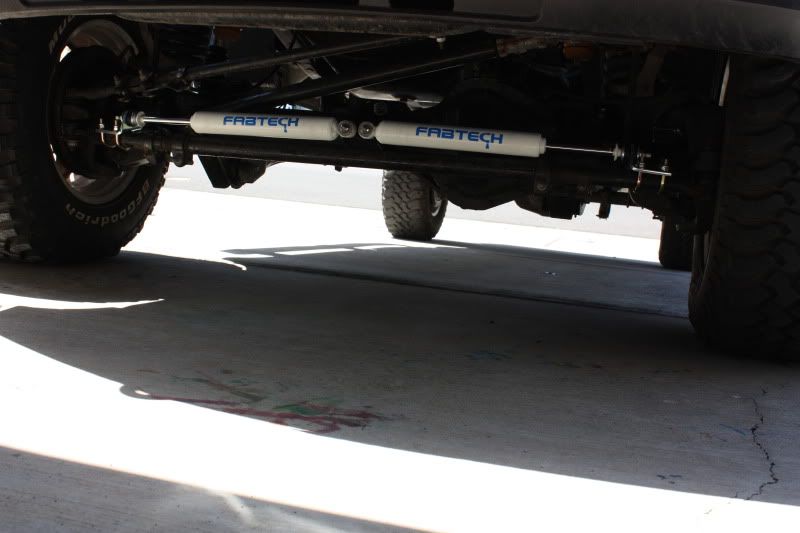
A steering stabilizer absorbs the tire shaking and prevents/tones it down alot. You basically bolt a shock to each tie rod end and they meet at a bracket bolted to the axle.
About $150 for a dual kit. Worth every penny
A steering stabilizer absorbs the tire shaking and prevents/tones it down alot. You basically bolt a shock to each tie rod end and they meet at a bracket bolted to the axle.
About $150 for a dual kit. Worth every penny
Trending Topics
MMNC (SS)(Ret)
Joined: Mar 2004
Posts: 11,606
Likes: 151
From: SE Georgia
FTE Stories
Ford Trucks for Ford Truck Enthusiasts

Top 10 Fords at 2026 Carlisle Ford Nationals
Joe Kucinski
3 Best / 3 Worst Parts of Modern Ford Ownership
Brett Foote
10 Amazing Upgrades That Solve Common Ford Truck Owner Headaches
Pouria Savadkouei
Every 2026 Ford Engine Explained
Brett Foote
10 Ugly Ford Trucks That We Still Kinda Love
Joe Kucinski
10 Things Every Truck Owner NEEDS (2026 Edition)
Michael S. Palmer
Rezvani's Latest Post-Apocalyptic Monster Is a Ford F-150 Raptor Underneath
Verdad Gallardo
Top 10 Most Expensive Ford Trucks Ever Sold on Bring a Trailer
Joe Kucinski
2027 Ford Super Duty Buyer's Guide (Every Model, Engine, & Package)
Brett Foote
Thread Starter
|
New User
Joined: Sep 2008
Posts: 42
Likes: 0
Just wanted to take a quick moment and say Thank You for all the help on this issue. Is was cool to such fast responses. Now I know what to look for. Thanks again and keep up the great work with novices like me.
FTE Leadership Emeritus


Joined: Sep 2000
Posts: 23,174
Likes: 1,678
From: Stephensville WI
TSB
05-22-1
STEERING WHEEL OSCILLATION
Publication Date: October 20, 2005
FORD:
2005-2006 F-Super Duty
This article supersedes TSB 4-26-01 to update the vehicle model years.
ISSUE:
Some 2005-2006 F-Super Duty vehicles may exhibit steering wheel oscillation (back and forth motion), immediately following front or rear wheel impacts (pavement joints, frost heaves, rough roads, etc.). Steering wheel motion is typically in the range of � 5 degrees, and typically dampens out in fewer than five oscillations. This condition occurs mostly on 4x4 vehicles, and is more evident on trucks equipped with a gas engine.
ACTION:
Refer to the following Service Procedure to minimize the steering wheel oscillations on impacts, however, there may be some remaining minor oscillation which would be considered normal.
SERVICE PROCEDURE
Perform the following:
Vehicle Inspection
Evaluation Of Vehicle Prior To Repair
Steering Gear Mesh Load Adjustment
Front Alignment and Reduce Front Caster
Replacement Of Redundant Control Steering Wheel (if equipped and vehicle built prior to 10/8/2004)
VEHICLE INSPECTION
Set tire pressures as indicated on the vehicle label (located on driver's door label).
NOTE: SETTING TIRE PRESSURE TO DOOR SPECIFICATION IS ONE OF THE SINGLE MOST IMPORTANT MEASURES IN RESOLVING THIS ISSUE. LOWERING TIRE PRESSURE WILL MAKE THIS ISSUE WORSE.
Wipe down and inspect the steering damper. Turn the steering wheel from lock to lock several times to cycle the steering damper and inspect for leaks.
If leaks are present, install a new steering damper and continue with this TSB.
If no leaks are present, continue with this TSB.
Check torques on the following steering and suspension fasteners and adjust to specification as required (see Table below).
Torque Specification
Description Lb-ft Nm
Damper nuts (4x2) 59 80
Damper-to-bracket (F-250, F-350 4x4) 26 35
Damper-to-drag link 67 91
Drag link-to-pitman arm nut 148 201
Inner tie-rod end nuts 85 115
Outer tie-rod end nuts 85 115
Track bar bracket-to-frame nuts and bolts 129 175
Track bar-to-track bar bracket bolt 406 550
Track bar-to-axle nut 185 250
Radius arm to axle bolts 222 300
Radius arm to bracket nut 222 300
NOTE: ADJUSTING TORQUE ON STEERING AND SUSPENSION FASTENERS IS VERY IMPORTANT IN RESOLVING THIS ISSUE. FASTENERS THAT ARE IMPROPERLY TORQUED WILL MAKE THIS ISSUE WORSE.
EVALUATION OF VEHICLE PRIOR TO REPAIR
Ask customer what type of road surface and speed generates the steering wheel oscillation.
Road test vehicle on similar road surface and speed, to gain a feel for the severity of wheel oscillation.
During the road test, evaluate and note the steering wheel return-ability.
Turn steering wheel full lock to lock to confirm no binding.
Locate center, and then 45 degrees either side of center on the steering wheel.
Driving vehicle at 35 MPH (56 Km/h), on a dry and flat road surface, turn the wheel 45 degrees and release. Note the approximate angle that the steering wheel returns to BEFORE CLEAR VISION. Perform and record the angle for both left and right. It is normal if the angle differs slightly from left to right.
STEERING GEAR MESH LOAD ADJUSTMENT
Insert hex wrench into steering gear mesh load adjuster screw.
While holding the mesh load adjuster screw tight, back off lock nuts two (2) full turns to allow free movement of the adjuster screw.
Carefully tighten adjuster screw until a slight increase in resistance is felt, then back off approximately 1/16th of a turn.
Hold the adjuster screw in place and tighten lock nut. Do not allow the adjustment screw to turn while tightening the locking nut down.
Road test vehicle and evaluate for improvement in steering wheel oscillations.
Confirm that there is no objectionable increase in steering efforts, especially at low speeds.
Verify that steering wheel return-ability is approximately the same as it was during the original evaluation (within 5 degrees).
Turn steering wheel full lock to lock to confirm no binding.
Park the vehicle to let it cool down. Road test cold to confirm acceptable parking efforts and return-ability in cold condition. Repeat the mesh load adjustment if needed.
FRONT WHEEL ALIGNMENT AND REDUCE FRONT CASTER
Measure wheel alignment. Verify that front caster, camber and total toe is within specification. Adjust as required. Refer to the Workshop Manual, Section 204-00 for complete alignment specifications.
REDUCE FRONT CASTER
Note the current front caster
Use alignment adjustment bushings to Reduce front caster by 0.5 to 0.75 degree. The caster setting may be at the lower end of the specification as long as the vehicle drives smoothly. Do not put caster setting below the lower specification limit. Use Alignment adjustment bushings.
F-250/350 4x4:
5C3Z-3B440-CCC (0.5 degree bushing)
5C3Z-3B440-DDD (0.75 degree bushing)
5C3Z-3B440-EEE (1.0 degree bushing)
F-450/550 4x4 and 4x2:
5C3Z-3B440-HHH (0.5 degree bushing)
5C3Z-3B440-JJJ (0.75 degree bushing)
5C3Z-3B440-KKK (1.0 degree bushing)
F-250/350 4x2:
5C3Z-3B440-C (0.5 degree bushing)
5C3Z-3B440-D (0.75 degree bushing)
5C3Z-3B440-E (1.0 degree bushing)
For All 4x4 and for F-450/550 4x2
Rotate the alignment adjustment bushing so that the bushing hole is in the 45 degree forward and inboard position (See Figure 1)
This should lower the caster, while keeping the camber within the specification range. If the camber is not in the specification range then rotate the alignment adjustment bushing as needed
The final caster and camber settings must be within the specification limits
Figure 1 - Article 05-22-1
Maintain the current front camber, cross-camber and cross-caster settings as close as you possibly can
Adding weight behind the rear axle lowers the rear of the vehicle, which decreases the frame angle, which in effect increases caster
Observe the camber position of the alignment bushing that is currently in the truck and attempt to maintain that position while moving the caster position forward in the truck
The final caster and camber settings must be within the specification limits
NOTE: CASTER SETTING IS VERY IMPORTANT IN RESOLVING THIS ISSUE. INCREASING THE CASTER SETTING WILL MAKE THIS ISSUE WORSE.
New User
Joined: Jun 2010
Posts: 20
Likes: 0
just rebuilt my front end from this. 2wd cc dually. my tie rod ends were wore a little, and had a little movement in the ball joints. pluse tightened down the steering box play a little.. since i did all that went and replaced all shocks on truck as well. all times it was fine, hit a set of bumps just right and would shake like crazy, would almost have to get bellow 45mph to get out of it.

FTE Leadership Emeritus

Joined: Sep 2003
Posts: 12,258
Likes: 766
From: Houston, Texas
Shake your booty...
Rebuild the front end, Moog tie rods and ball joint, and add these: https://www.ford-trucks.com/forums/1...ure-video.html
The video speaks for itself, Special Thanks to EpicCowlick!
The video speaks for itself, Special Thanks to EpicCowlick!
Hotshot
Joined: Mar 2007
Posts: 10,101
Likes: 40
From: Pa
I wouldn't just go throwing parts at it hoping the parts fix the issue.
I would inspect everything for excess play and make sure the fasteners/bolts/nuts are tight. Wouldn't hurt to get an alignment to make sure everything is correct as per the TSB. If everything checks out ok you could try a dual steering stabilzer setup.
I would inspect everything for excess play and make sure the fasteners/bolts/nuts are tight. Wouldn't hurt to get an alignment to make sure everything is correct as per the TSB. If everything checks out ok you could try a dual steering stabilzer setup.

Junior User
Joined: Dec 2005
Posts: 56
Likes: 2
From: west of Cleveland Oh
I had the death wobble with my 05 Thanks to the great guys in this forum I haven't had it in the last 5k miles! My fix- set the tire pressures correctly and installed dual steering stabilizer. Problem solved! by the way my o5 only had 26k on it when I first experienced death wobble. At 70mph in am rush hour traffic on 8 lane freeway I needed toiet paper! Thanks guys!

Thread
Thread Starter
Forum
Replies
Last Post
jeeplj8
Excursion - King of SUVs
6
Dec 23, 2011 08:59 AM
SUPERDUTY OUTLAW
1999 - 2003 7.3L Power Stroke Diesel
13
Apr 25, 2010 04:32 PM
NorthPac
1983 - 2012 Ranger & B-Series
7
Jun 19, 2006 08:44 AM
Ohiogal
1987 - 1996 F150 & Larger F-Series Trucks
3
Jul 17, 2004 06:57 AM