


Overhead display Fix

Junior User
Joined: Nov 2003
Posts: 59
Likes: 0
I too was having problems with my overhead display and read this thread. Came off easily using the cited procedure and I sent it off to Auto Clock Repair.
Auto Clock Repair - Home
I placed in a bubble wrap envelope and sent priority mail with a check for $36 and change. Just got it back (<2 weeks turn-around) and works like a gem with a lifetime warranty. I recommend this company based on my experience.
Auto Clock Repair - Home
I placed in a bubble wrap envelope and sent priority mail with a check for $36 and change. Just got it back (<2 weeks turn-around) and works like a gem with a lifetime warranty. I recommend this company based on my experience.
Thread Ender
Joined: Dec 2010
Posts: 1,296
Likes: 8
From: SC

I am definitely no electrical wizard or electronics solderer and I have done this fix on an Ex and an F350 and would highly recommend doing it yourself rather than shipping it off and paying someone to do it. Both times, when pulling the unit down, the resistors in question have been laying inside the black cover. The first time I had to buy the $15 soldering iron from radio shack and some skinny solder and so I spent about $18. This time, since I already had that, I spent no $$$ and about 15 minutes and plugged it back up at it works fine. When soldering the tiny resistors, you really dont have to be that precise.

Cross-Country
Joined: Jul 2003
Posts: 95
Likes: 2
It works!
Did what you said by resoldering those chips and it worked! None of the chips were loose but I did it anyway...I figured I had nothing to lose! Kinda reminded me of soldering/refloating joints on the FICM. That worked for about 8 months before it failed again...
(2004 Ex, diesel, LTD)
Here's a pic of the overhead console. Black box in lower part of the picture is the lie-o-meter. Removal instructions were as mentioned except for the screw in the sunglass holder. I'm glad someone mentioned that or I might have ripped the thing out of the ceiling!

Close up of the lie-o-meter box in the console. You can see the three torx screws and the wiring harness you have to remove.

Side of the box where you can see two of the four clips you disengage to open the housing.

The other two clips.

Back cover removed. I ended up refloating all the solder in the three wide areas you see on the top left side of the circuit board. I held a damp sponge on the other side against the chips to keep them from falling off.

In this picture you can see the seven chips to the right of the display screen. Four of them are between the screen and the Red M&M; the other three are below them oriented 90 degrees from the others.

Thought I'd add some pictures to the discussion while I was at it! Happy New Year and happy motoring!
(2004 Ex, diesel, LTD)
Here's a pic of the overhead console. Black box in lower part of the picture is the lie-o-meter. Removal instructions were as mentioned except for the screw in the sunglass holder. I'm glad someone mentioned that or I might have ripped the thing out of the ceiling!
Close up of the lie-o-meter box in the console. You can see the three torx screws and the wiring harness you have to remove.
Side of the box where you can see two of the four clips you disengage to open the housing.
The other two clips.
Back cover removed. I ended up refloating all the solder in the three wide areas you see on the top left side of the circuit board. I held a damp sponge on the other side against the chips to keep them from falling off.
In this picture you can see the seven chips to the right of the display screen. Four of them are between the screen and the Red M&M; the other three are below them oriented 90 degrees from the others.
Thought I'd add some pictures to the discussion while I was at it! Happy New Year and happy motoring!
Thread Starter
|
Senior User

Joined: Oct 2010
Posts: 440
Likes: 0
From: Ft Worth
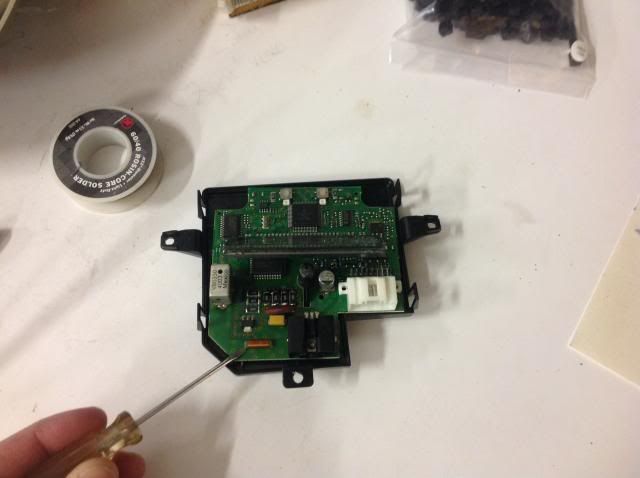
We were having issues with the compass not working or saying it needs to be cal'ed. So I took ours apart again and found the coil (pointing at it with the screwdriver) looking component loose. I re-soldered it and it seems to be working fine again. (don't look at my crappy solder jobs though)

FTE Legend


Joined: Jan 2006
Posts: 37,918
Likes: 178
From: Princeton, BC
I smacked mine and it worked, then it quit all together. Then it came back. I took it apart and found something loose. I soldered that and it worked for a bit then quit.
I just sent mine out to have it repaired. Price with shipping was 62 bucks and change. Better than the 400 they want for a new one here.
I just sent mine out to have it repaired. Price with shipping was 62 bucks and change. Better than the 400 they want for a new one here.
FTE Stories
Ford Trucks for Ford Truck Enthusiasts

Top 10 Fords at 2026 Carlisle Ford Nationals
Joe Kucinski
3 Best / 3 Worst Parts of Modern Ford Ownership
Brett Foote
10 Amazing Upgrades That Solve Common Ford Truck Owner Headaches
Pouria Savadkouei
Every 2026 Ford Engine Explained
Brett Foote
10 Ugly Ford Trucks That We Still Kinda Love
Joe Kucinski
10 Things Every Truck Owner NEEDS (2026 Edition)
Michael S. Palmer
Rezvani's Latest Post-Apocalyptic Monster Is a Ford F-150 Raptor Underneath
Verdad Gallardo
Top 10 Most Expensive Ford Trucks Ever Sold on Bring a Trailer
Joe Kucinski
2027 Ford Super Duty Buyer's Guide (Every Model, Engine, & Package)
Brett FooteJunior User
Joined: Dec 2013
Posts: 65
Likes: 1
From: Metro Detroit, MI
Compass WORKS!!
We were having issues with the compass not working or saying it needs to be cal'ed. So I took ours apart again and found the coil (pointing at it with the screwdriver) looking component loose. I re-soldered it and it seems to be working fine again. (don't look at my crappy solder jobs though)
Thanks again,
Sean

Senior User
Joined: Oct 2012
Posts: 470
Likes: 1
From: Havillah, WA
These are the guys i'll end up using. http://www.ebay.com/itm/250626050798?_trksid=p2055119.m1438.l2649&ssPageName=STRK%3AMEBIDX%3AIT
I took mine apart but once i saw the size and location of the chips behind the display i figured no way i was gonna attempt that and mess something else up worse or break the display trying to bend it out of the way.
I'm pretty sure these guys replace the resistors with normal sized ones with leads on them so they're soldered on well. They also fix the compass if there's issues with that contact. I've just been too lazy to take mine back out and be without it for 7 days

Tuned
Joined: Aug 2013
Posts: 344
Likes: 1
From: Phoenix, AZ
Resoldered the resistors on the board but its still too dim when the lights are on during the day and you are wearing sunglasses. Next step is to replace the resistors to increase the brightness. I will post up some instructions once I have the numbers and which ones are lights on vs lights off.