


I terminel on reg.

Thread Starter
|
Senior User
Joined: Nov 2010
Posts: 172
Likes: 0
From: Warren, NJ
I terminel on reg.
Looks like transister reg. on my truck. I terminal runs to amp. on drawing. If i'm using original inductive gauge do i not use I terminal. Oh yea, Okay to use original gauge with 12 Volts? Thanks Bob

Post Fiend
Joined: May 2008
Posts: 7,641
Likes: 21
From: Poway, Ca.
With an inductive gauge you are monitoring flow direction first and the amount second. It is simply a "yes the alternator is providing power to the truck (charging), or no the battery is supplying the power (discharging).
So, the inductive ammeter needs to be on the flow path between the charging source (generator or alternater) on one end and the battery on the other.
Your power distribution - fuse blocks, ignition switch, whatever- need to be between the charging source and the gauge, with the final length of the wire running directly from the gauge to the point where it connects to the battery.
On a 12 volt Ford, thats the starter solenoid lug that the positive battery cable attaches to.
The "I" post/wire on a modern alternator regulator will only work with a true ammeter with hard electrical connections but is designed for charge lights, not meters.
That type of traditional electrical flow is shown in the first drawing.
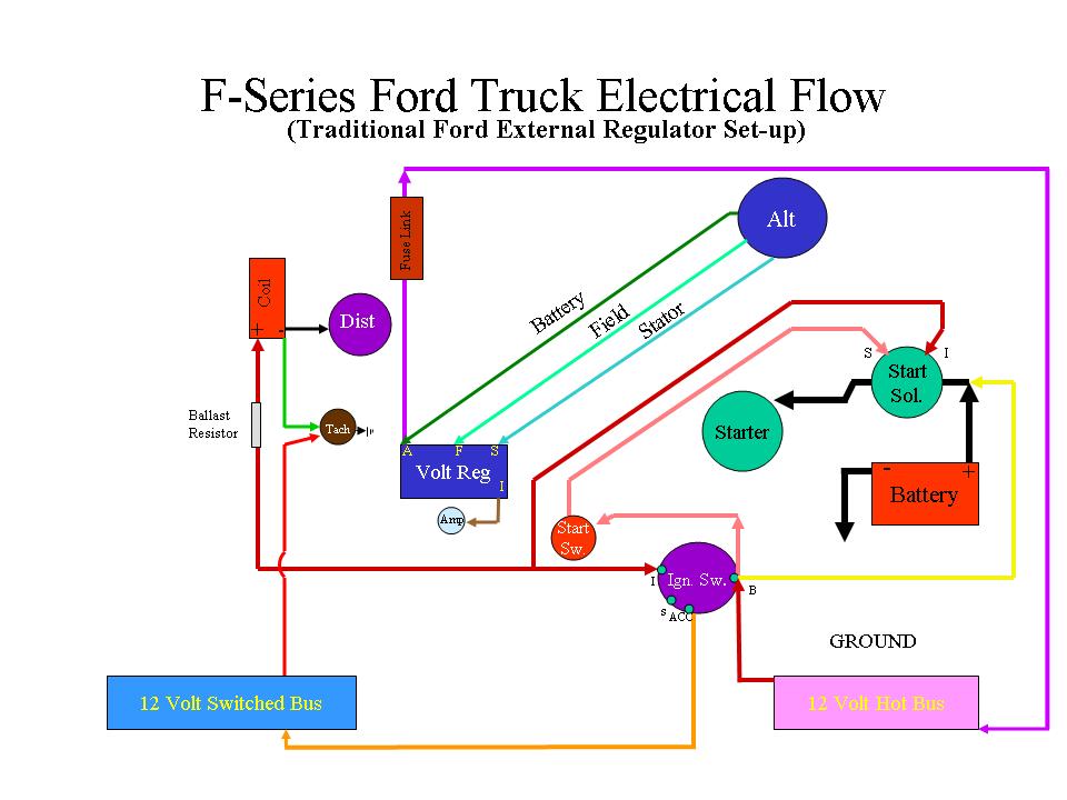
With this set up your inductive ammeter would be on the yellow wire between the ignition switch and starter solenoid, not off the "I" wire as shown.
P.S. A "BUS" is a fuse block for distributing power. "HOT" is powered all the time, "SWITCHED" provides power when the ignition switch is turned on.
So, the inductive ammeter needs to be on the flow path between the charging source (generator or alternater) on one end and the battery on the other.
Your power distribution - fuse blocks, ignition switch, whatever- need to be between the charging source and the gauge, with the final length of the wire running directly from the gauge to the point where it connects to the battery.
On a 12 volt Ford, thats the starter solenoid lug that the positive battery cable attaches to.
The "I" post/wire on a modern alternator regulator will only work with a true ammeter with hard electrical connections but is designed for charge lights, not meters.
That type of traditional electrical flow is shown in the first drawing.
With this set up your inductive ammeter would be on the yellow wire between the ignition switch and starter solenoid, not off the "I" wire as shown.
P.S. A "BUS" is a fuse block for distributing power. "HOT" is powered all the time, "SWITCHED" provides power when the ignition switch is turned on.
Fleet Owner


Joined: Jul 2004
Posts: 27,294
Likes: 1,055
From: NM
I was under the impression this is a solid-state voltage regulator on a generator? Bob, what drawing were you referring to? Can you post it? We need more info to understand what is going on and what you have. Pictures of the generator or alternator and regulator would help.
Julie, I don't see why you are saying the I terminal on a modern alt. only works with a hard-terminal ammeter? Whether the current is picked up inductively or with a shunt, the power is flowing thru the ammeter to the loads.
Julie, I don't see why you are saying the I terminal on a modern alt. only works with a hard-terminal ammeter? Whether the current is picked up inductively or with a shunt, the power is flowing thru the ammeter to the loads.
Trending Topics
Post Fiend
Joined: May 2008
Posts: 7,641
Likes: 21
From: Poway, Ca.
When they are wired that way they are wired directly to the battery and bypass the power distribution. Thus, if there is a failure on the part of the alternator, a hard wired gauge will sense a discharge at the battery. Being hardwired the needle is physically pulled because of the electrical configuration of the hardwired gauge itself.
But if you put an inductive gauge on that line, it will show a charge, but in the event of a failure, the batter will supply power back through the primary wiring to the power distribution without it flowing through the gauge thus you will only see a charge on the gauge or a neutral indication, never a charge.
In the case with our trucks, we don't use power off the stator wire because of power distribution note there's no fuse blocks in these two diagrams. These traditional Ford systems distribute power completely differently. And the type and placement of Power Disribution is the critical elliment in getting a proper dischrage indication.
BTW, I posted thes drawings for the purpose of showing the differences between gauge and meter hook up. Not to suggest that this is the appropriate wiring schematic for our applications.
FTE Stories
Ford Trucks for Ford Truck Enthusiasts

Rezvani's Latest Post-Apocalytic Monster Is a Ford F-150 Raptor Underneath
Verdad Gallardo
Top 10 Most Expensive Ford Trucks Ever Sold on Bring a Trailer
Joe Kucinski
2027 Ford Super Duty Buyer's Guide (Every Model, Engine, & Package)
Brett Foote
Top 10 Ford Truck Tragedies
Joe Kucinski
AEV FXL Super Duty - the Super Duty Raptor Ford Doesn't Make
Brett Foote
Lobo Vs Lobo: Proof the F-150 Lobo Should Be Even Lower!
Michael S. Palmer
Ford's 2001 Explorer Sportsman Concept Looks For a New Home
Verdad Gallardo
10 Best Ford Truck Engines We Miss the Most!
Joe Kucinski
2026 Shelby F-150 Off-Road: Better Than a Raptor R?
Brett Foote
Thread Starter
|
Senior User
Joined: Nov 2010
Posts: 172
Likes: 0
From: Warren, NJ
Sorry for the confusion. The drawing i was refering to was the one just posted by Julie. Traditional ford external electrical set-up. I understand where the inductive guage is. Since i'm going to use that guage I just wanted to know if it was okay to not connect the I wire off the reg to anything at all.

Post Fiend
Joined: May 2008
Posts: 7,641
Likes: 21
From: Poway, Ca.
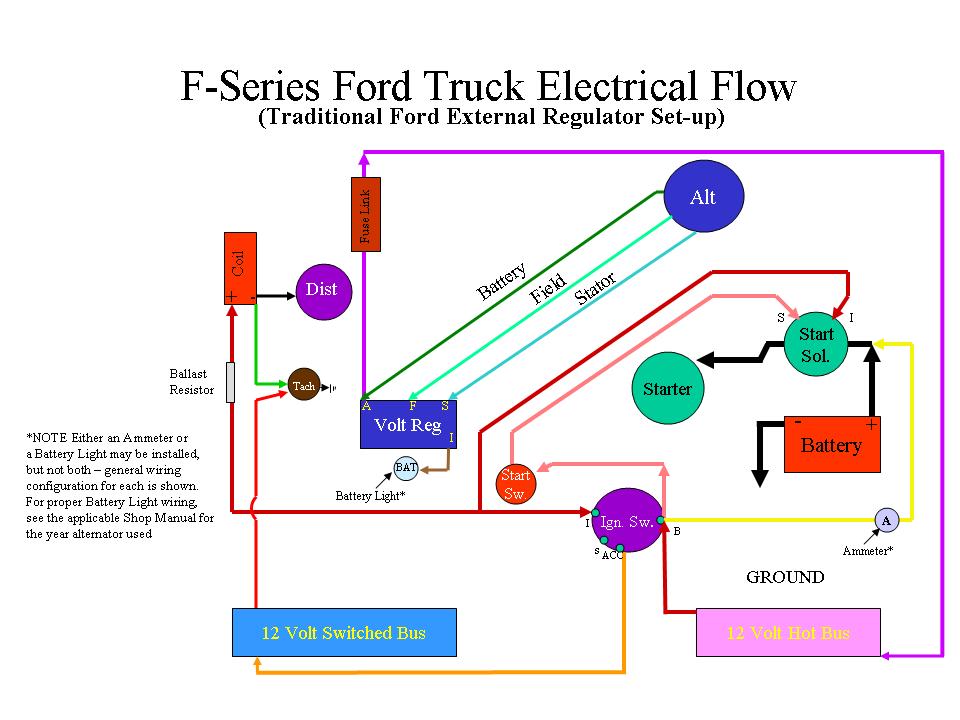
Yes, that's correct. I haven't used that drawing for years. When I made it up it was for a specific persons system and the "Battery Light" as "A" was understood at the time. Since I've used it as a general guide, I'll update it to show "general" configuration. Use the same drawing but for your inductive ammeter on that yellow wire between the ignition switch and starter solenoid.
Ross, there are many many different changes in the configuration on these systems between our trucks and today. Some were like the pics I posted, some needed exciter wires, shunts, etc. Kind of hard to filter out.
So I just passed on what would work for him without getting too much into detail - there's just too many possible configurations, and they're all different.
Edit Note: Here's the modified drawing:

Thread
Thread Starter
Forum
Replies
Last Post
preferred88
1973 - 1979 F-100 & Larger F-Series Trucks
6
May 16, 2016 09:46 AM
Big_Al59
1987 - 1996 F150 & Larger F-Series Trucks
4
Jan 29, 2011 12:47 AM
250-highboy-76
1967 - 1972 F-100 & Larger F-Series Trucks
1
Apr 30, 2006 05:56 AM