


Ideal Castor Setting?

Lead Driver
Joined: Jun 2007
Posts: 6,757
Likes: 5
From: Corvallis, OR
Ideally, you want the pinion parallel with the transfer case output shaft. However, this breaks down with really big lifts when the u-joint angles get too large, which is why they begin clocking the transfer cases to lower the output yoke.
Senior User
Joined: Mar 2007
Posts: 204
Likes: 0
From: Qld Australia
There's no hope of getting anywhere near parallel with the transfer case shaft. (It is parallel with the engine and transmission which slope down at the rear, keeping the rear drive-shaft close to straight.) Which is why a double-cardan joint is fitted to the the transfer case end of the front drive shaft and the front pinion shaft is very close to inline with the front drive shaft. Which gives you a little latitude when it comes to rotating the front diff housing to obtain more castor angle.
Lead Driver
Joined: Jun 2007
Posts: 6,757
Likes: 5
From: Corvallis, OR
The rear pinion you can easily get parallel. The front, I'm not sure about as the pinion would have to be angled down as you said. Maybe they don't worry about it on the front since you don't travel at high speeds in 4wd.
Senior User
Joined: Mar 2007
Posts: 204
Likes: 0
From: Qld Australia
Nothing to do with speed. Some nut will invariably forget to disengage 4WD. Besides, 4WD can be beneficial on fast gravel roads too.
The geometry of the whole thing simply requires the double-cardan joint to accommodate the large angle on the front of the transfer-case. There's no avoiding it. But by using one, the other end (front end) of the front drive shaft doesn't need to run with much angle at all. Hence the front diff pinion shaft is aimed close to in-line with the drive shaft and double-cardan joint. This is the preferred arrangement for a suspension set-up that uses radius arms or 3-link, like the factory set-up. Nothing wrong with that either. The only minor downside is that the castor angle varies with ride height. Hence doing large lifts you need to rotate the diff housing to maintain enough castor angle. Just as the OP is designing into his mods.
The geometry of the whole thing simply requires the double-cardan joint to accommodate the large angle on the front of the transfer-case. There's no avoiding it. But by using one, the other end (front end) of the front drive shaft doesn't need to run with much angle at all. Hence the front diff pinion shaft is aimed close to in-line with the drive shaft and double-cardan joint. This is the preferred arrangement for a suspension set-up that uses radius arms or 3-link, like the factory set-up. Nothing wrong with that either. The only minor downside is that the castor angle varies with ride height. Hence doing large lifts you need to rotate the diff housing to maintain enough castor angle. Just as the OP is designing into his mods.
Thread Starter
|
Senior User
Joined: Nov 2006
Posts: 241
Likes: 0
From: Southern California
thanks for the discussion, fellas! the main thing I'm interested is the angle of the pinion in relation to the driveshaft... I'm currently running only the deaver 2" mini pack so that angle changed a bit but not nearly enough to worry...
now, with a radius arm setup, the castor and the driveshaft angle so to speak changes with it (another way to look at it is the pinion angle changes with the castor)...
with a conventional 3 or 4-link (no panhard bar), then the angles move similar to a radius arm setup...
my setup (parallel 4-link w/ panhard bar) doesn't change the castor or pinion angle as it goes through travel... because of this, the angle of the driveshaft changes quite a bit... haven't gotten all the numbers yet, but I will within the next week or so... for the record, truck is getting 3 or 4" lift over stock at most... trying to keep the truck as low as possible and run 37" tires...
soooo... whats the stock pinion angle and castor? haha
a related question: where can I get a model of a heim joint? I found some on 3dcontentcentral but they don't seem to work with my version or solidworks... 2010 SW Student edition... need these so I can start cycling stuff...
Joey
Senior User
Joined: Mar 2007
Posts: 204
Likes: 0
From: Qld Australia
For a 4-link setup, ideally you would have no joint angle when halfway through the ride height range. However, you're not really going to be able to alter this - you need to set the desired castor angle and hope the pinion angle will be right. And I'm confident it will be close enough not to be an issue at all.
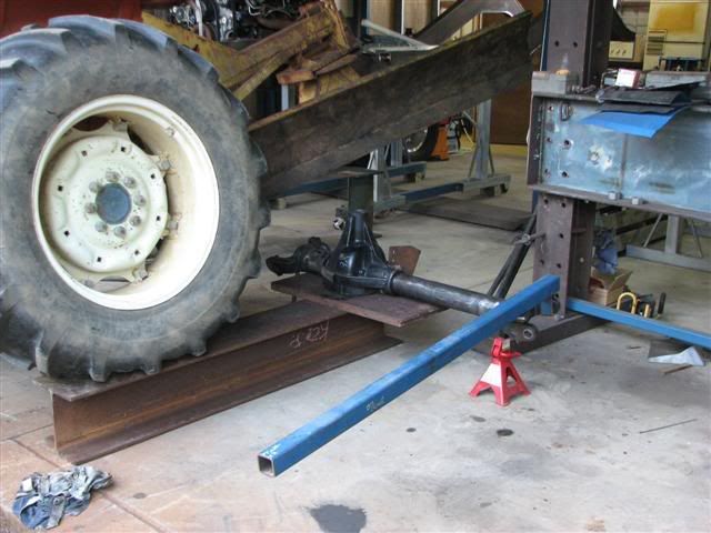
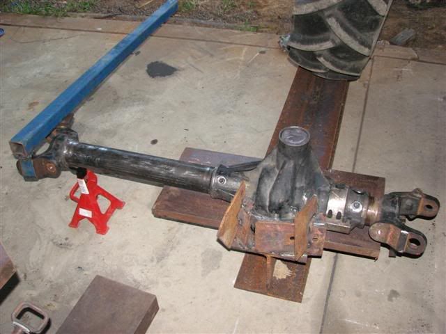
Now if you do want to alter the relationship between the pinion shaft and the castor angle, you'll need to do something like I did with my project build.
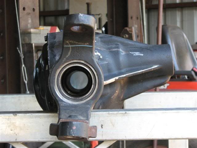
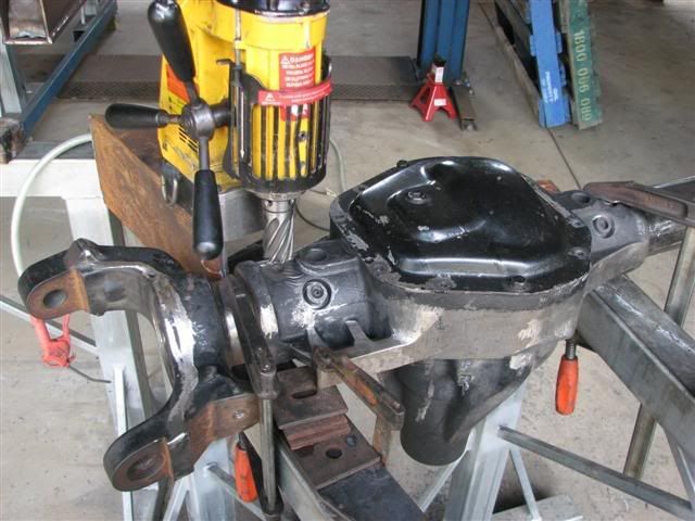
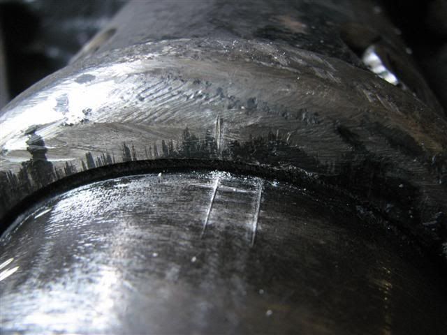
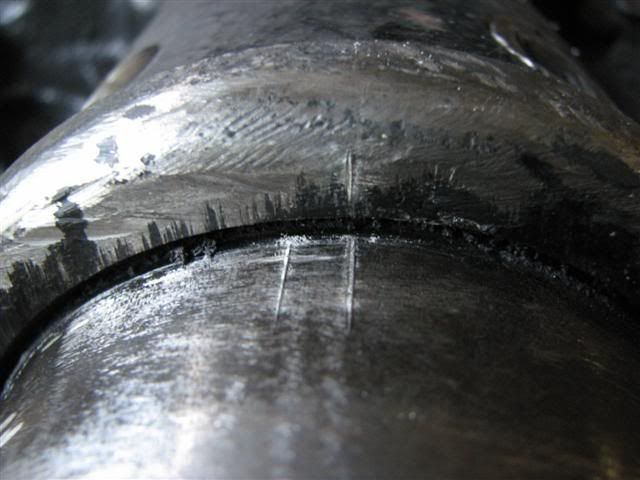
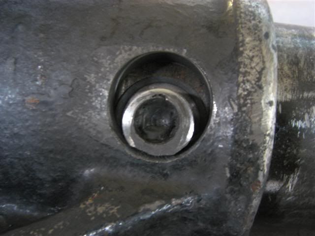
If you're wondering what's with the rota-broach, it's because the factory plug welds fixing the axle tubes to the cast diff centre is as hard as nails. Undrillable. So I just cut right around them.
Let me know if you would like more.
Now if you do want to alter the relationship between the pinion shaft and the castor angle, you'll need to do something like I did with my project build.
If you're wondering what's with the rota-broach, it's because the factory plug welds fixing the axle tubes to the cast diff centre is as hard as nails. Undrillable. So I just cut right around them.
Let me know if you would like more.

Junior User
Joined: Sep 2010
Posts: 80
Likes: 0
GM solid axle trucks run as much as 7 degrees of castor,if your long travel suspension loses castor as it drops, you need to have enough so that you do not go positive or it will get squirrelly as the suspension cycles. Positive castor adds camber tothe outside wheel when cornering, but will increase tire wear on a street driven truck.
FTE Stories
Ford Trucks for Ford Truck Enthusiasts

2027 Ford Super Duty Buyer's Guide (Every Model, Engine, & Package)
Brett Foote
Top 10 Ford Truck Tragedies
Joe Kucinski
AEV FXL Super Duty - the Super Duty Raptor Ford Doesn't Make
Brett Foote
Lobo Vs Lobo: Proof the F-150 Lobo Should Be Even Lower!
Michael S. Palmer
Ford's 2001 Explorer Sportsman Concept Looks For a New Home
Verdad Gallardo
10 Best Ford Truck Engines We Miss the Most!
Joe Kucinski
2026 Shelby F-150 Off-Road: Better Than a Raptor R?
Brett Foote
2027 Super Duty Carhartt Package First Look: 12 Things You NEED to Know!
Michael S. Palmer
10 Most Surprising 2026 Ford Truck Features!
Joe KucinskiThread Starter
|
Senior User
Joined: Nov 2006
Posts: 241
Likes: 0
From: Southern California
well, at ride height it will be close to stock (about 3-4" over stock, have yet to take that measurement)... I guess I'll just go off of that, cycle it in solidworks and see what I come up with... thanks for the pics, DJ... I've heard of people turning the axle tubes the way you did to correct that angle... my lift isn't extreme at all and neither is the travel I'm looking to get (10-12" bumped/strapped) so not seeing myself doing that...
so any suggestions on models for heim joints? I can make my own in sw but that'll just add time that could otherwise be spent on cycling and doing the math... thanks again, fellas...
oh, and this is how far along I am... and cut me some slack, still learning haha... and have yet to get a tape measure under the truck, but won't happen until next week hopefully...

and once I get all the measurements done, may put the model on trails less traveled of the axle... not the brackets haha...
Joey
so any suggestions on models for heim joints? I can make my own in sw but that'll just add time that could otherwise be spent on cycling and doing the math... thanks again, fellas...
oh, and this is how far along I am... and cut me some slack, still learning haha... and have yet to get a tape measure under the truck, but won't happen until next week hopefully...
and once I get all the measurements done, may put the model on trails less traveled of the axle... not the brackets haha...
Joey
Senior User
Joined: Mar 2007
Posts: 204
Likes: 0
From: Qld Australia
I admire your thorough approach Joey.
And keeping to a modest lift is so much more sensible too.
I never did get the hang of SolidWorks. I would dearly like to to be able to cycle through the range of movement in a suspension system like you are doing. I only got as far as AutoCAD. And had to draw everything three times over, at full compression, full droop, and fully articulated, to see that everything worked ok.
This is as far as I went with it. Wish I had the time to start over in SolidWorks....
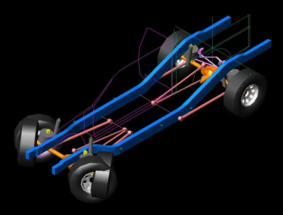
You are welcome to a copy of that drawing if you think it is of any use. The wheels and axles are very close to the real thing. The chassis is my design though so won't help you much.
And keeping to a modest lift is so much more sensible too.
I never did get the hang of SolidWorks. I would dearly like to to be able to cycle through the range of movement in a suspension system like you are doing. I only got as far as AutoCAD. And had to draw everything three times over, at full compression, full droop, and fully articulated, to see that everything worked ok.
This is as far as I went with it. Wish I had the time to start over in SolidWorks....
You are welcome to a copy of that drawing if you think it is of any use. The wheels and axles are very close to the real thing. The chassis is my design though so won't help you much.
Thread Starter
|
Senior User
Joined: Nov 2006
Posts: 241
Likes: 0
From: Southern California
thanks for the kind words, buddy... yeah, I first learned Pro-Engineer and while the program while is very robust, solidworks from what I can tell is better for my application... plus I can cycle everything, get angles and whatnot...
so, decided to go back to radius arms because I don't feel like spending $500 on heims alone... besides, because of the the length of the lower link, I shouldn't get much castor change and I was going to design some into the 4-link anyways... I want to finish the truck before summer is over and won't be able to afford it with running (8) 1-1/4" heims @ $125 for a set of 2 lol... aaaand I was able to get ahold from another member the heims I needed...
Joey
Thread Starter
|
Senior User
Joined: Nov 2006
Posts: 241
Likes: 0
From: Southern California
since I'm a broke college student now, don't really have the money to buy stuff I need... well, not in a hurry anyways, lol... but designing and getting it all mocked up in solidworks is free, and I have plenty of time... so this is where I'm at so far:

all the angles and dimensions are pretty much correct, just have to remeasure them to make 100% sure... the upper mount is designed to be where the truck will bump off of and directly at the center of the axle tube while the lower will be as low as I can possible get it... spread is about 5" between the two mounting points and the links look like they will be in the neighborhood of around 32" or so... still have to model the frame side brackets and the axle ones, as well, since the ones designed right now are just for reference... what do you guys think? all the angles are based on a 2" lift over stock up front... once its all modeled, then I can start cycling it...
Joey
Senior User
Joined: Mar 2007
Posts: 204
Likes: 0
From: Qld Australia
Good to see you're still on to it!
Only thing I've got to mention so far is that the 5" of separation might be a bit small. Just keep in mind the rather immense torque loading there is when you stomp on the brakes on a good sealed surface. All that force is trying to rotate the whole axle housing assembly forward and the radius arms must be attached well enough to resist that force. The original arms have those large hard rubber bushes separated by a good 8" if I remember right. They work fine of course, but they also act as a big sway-bar too. Which is fine on the road, but is limiting to the amount of articulation possible off-road. Also, the rubber bushes can't simply be replaced by nice big heim joints or similar with no give in them. Otherwise the axle will only be permitted to swing up and down and not articulate over uneven ground. Something will end up breaking.
With that in mind you can see how using fixed arms as Ford does is a compromise. If you were to remove one bush it would allow for plenty of articulation, but all the torque loading would be via only one arm. Not likely to go down well with your DoT inspectors.
Then the other issue when it comes to modifying anything to do with the arm mounts on the axle is that the left side bushes are mounted into castings of the diff centre. Making doing anything much there very difficult. So to increase the castor angle by much you either lower the arm mounting points on the chassis, fit arms with modified geometry. Both of which will increase the angle of the front uni-joint. Or, you rotate the axle tubes in the diff centre and rhs bracket. Which keeps the uni-joint straight but is a big big job.
Personally if I were in your shoes and don't intend to do anything to serious off-road, I would work out how far you need to move the bottom bush bolt hole in the radius arms. It might only be a few millimetres. Fill the existing holes in, drill the new hole and then weld a washer in place on the new hole. This would get your desired castor angle. The pinion angle would be more than ideal but I think it would still be well within acceptable limits. This would be the simplest and cheapest option too.
Thread Starter
|
Senior User
Joined: Nov 2006
Posts: 241
Likes: 0
From: Southern California
Thanks for the reply! and I'm not too worried on the separation, although I would rather have at least 6" between them...

this is a kit made by a company (the name slips me right now) that converts the front end to coilovers, and the spread doesn't seem to be too far from what I have... I may be able to move the lower mount on the axle a little lower but not much... and these numbers aren't set in stone yet, as more than likely I will HAVE to move the upper a little higher, depending on how much of a lift I need to fit the 12" saw's without cutting into my engine bay...
and I know what you're saying about the rubber bushings, which is why I'll be running 3 bushings and 1 heim per side... should be enough rubber to allow the axle to twist and the heim will actually let the truck articulate...
I think you're forgetting that I'm converting my truck from leaf springs to radius arms... so, I don't have any mounts on either side... I have to design a bracket that wraps around the axle/leaf perch and serves as the mounting for the radius arm, bump pad, and lower coilover mount... already have a good idea on the design in my head and on paper... trying to design the entire thing as a "kit" with a minimum amount of cutting/welding, mainly because, after enough testing, I would like to market this as nobody makes an affordable kit and a minimum lift for the super donkeys...
as for design of the radius arm, it'll be a 2" OD lower bar that run from the frame to lower mount with a heim on the frame side (threaded for adjustability) and a rubber bushing on the axle side (hard mount)... then I'll have a 1.75" OD tube run from the upper axle mount (rubber hard mount) to the lower, main tube with a threaded, rubber bushing to be able to adjust the castor... stay tuned!
Joey
Senior User
Joined: Mar 2007
Posts: 204
Likes: 0
From: Qld Australia
At least you haven't so much casting in the way, making it easier to work with.
Now there's a great idea! Looking forward to seeing that.