


03 Door Ajar Indicator Switch Replacement Process
Thread Starter
|
Tuned


Joined: Aug 2007
Posts: 458
Likes: 120
From: Maryland
03 Door Ajar Indicator Switch Replacement Process
To start off, I've been through about three dousings with the WD40, which worked well....until this last time. After emptying two cans, I figured time to open up some doors. Each door was opened up, removed the door panels, disconnected the harness from the door ajar sensor switches, and install a temporary jumper to isolate the problem. In true Murphy fashion, I started at the tailgate and finished up at the drivers door, where, come to find out, the problem existed. Suggestion one would be to start your search at the drivers door, likely the culprit with the most use. I left my temporary jumper in the harness while the switch/sensor was placed on order....no one had it in stock. I would have taken pictures of the initial fiasco, but trying to work after dark and take pictures as well......it didn't happen. Once the switch came in I had a nice sunny day for replacement, so I thought to show the process for those wishing to tackle it themselves....
03 driver's door panel:
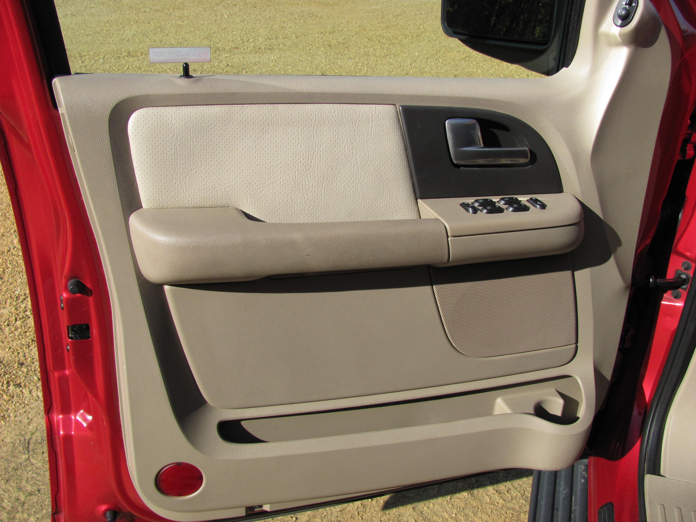
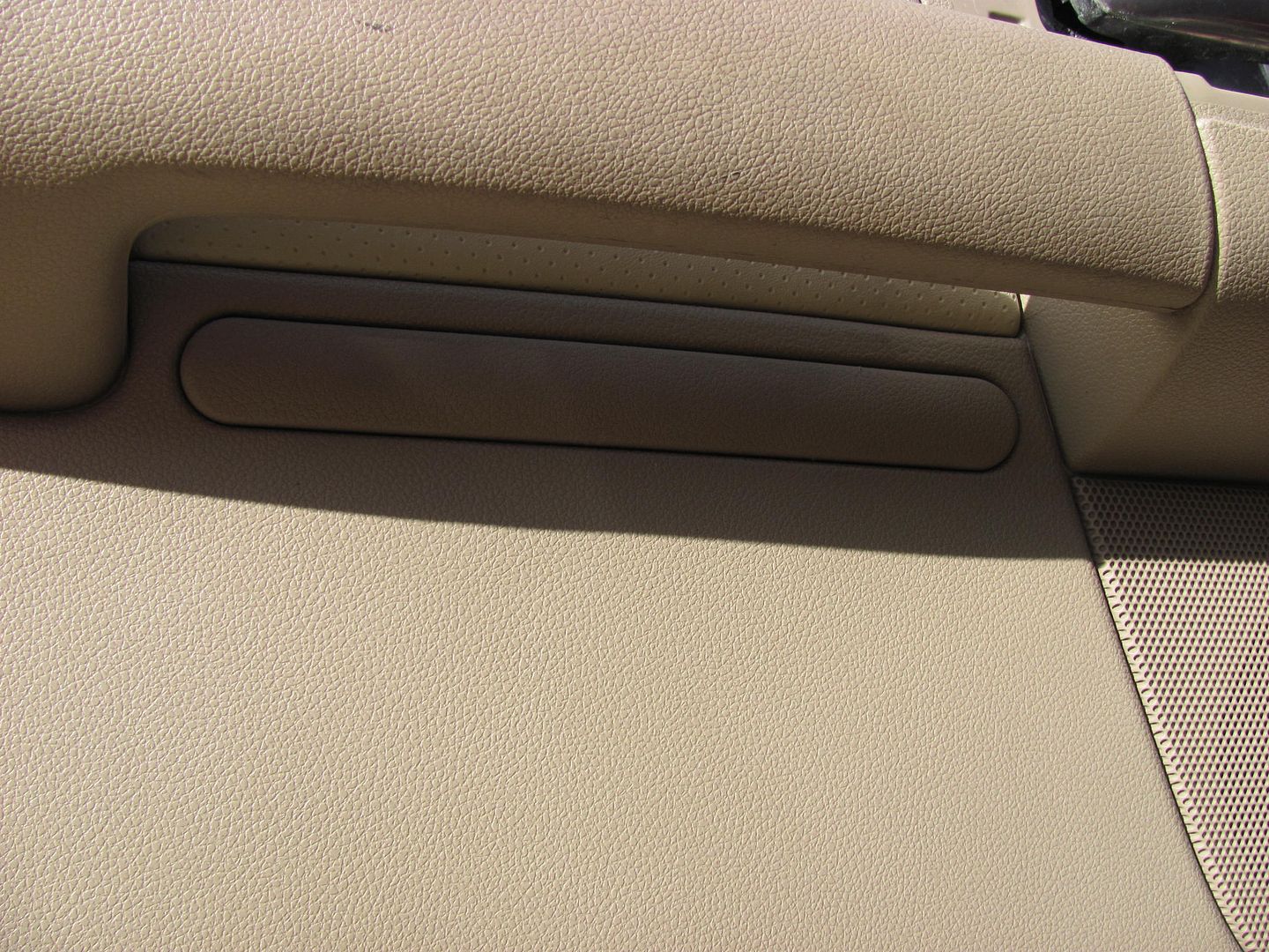
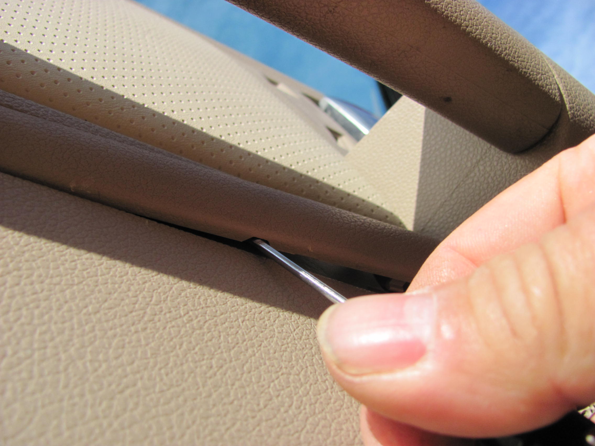
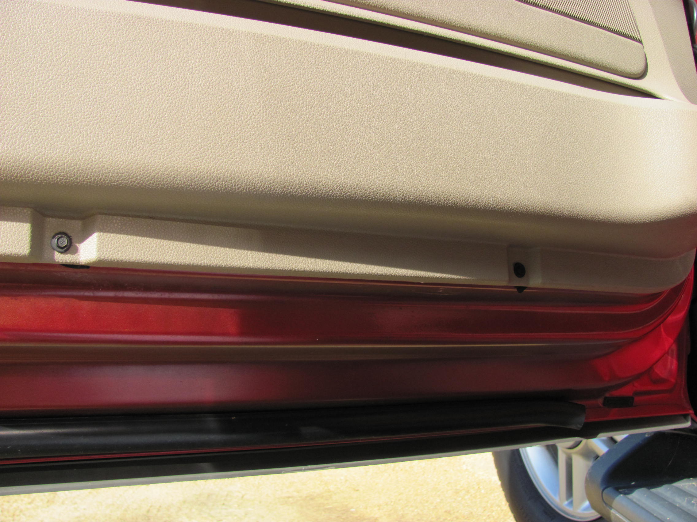
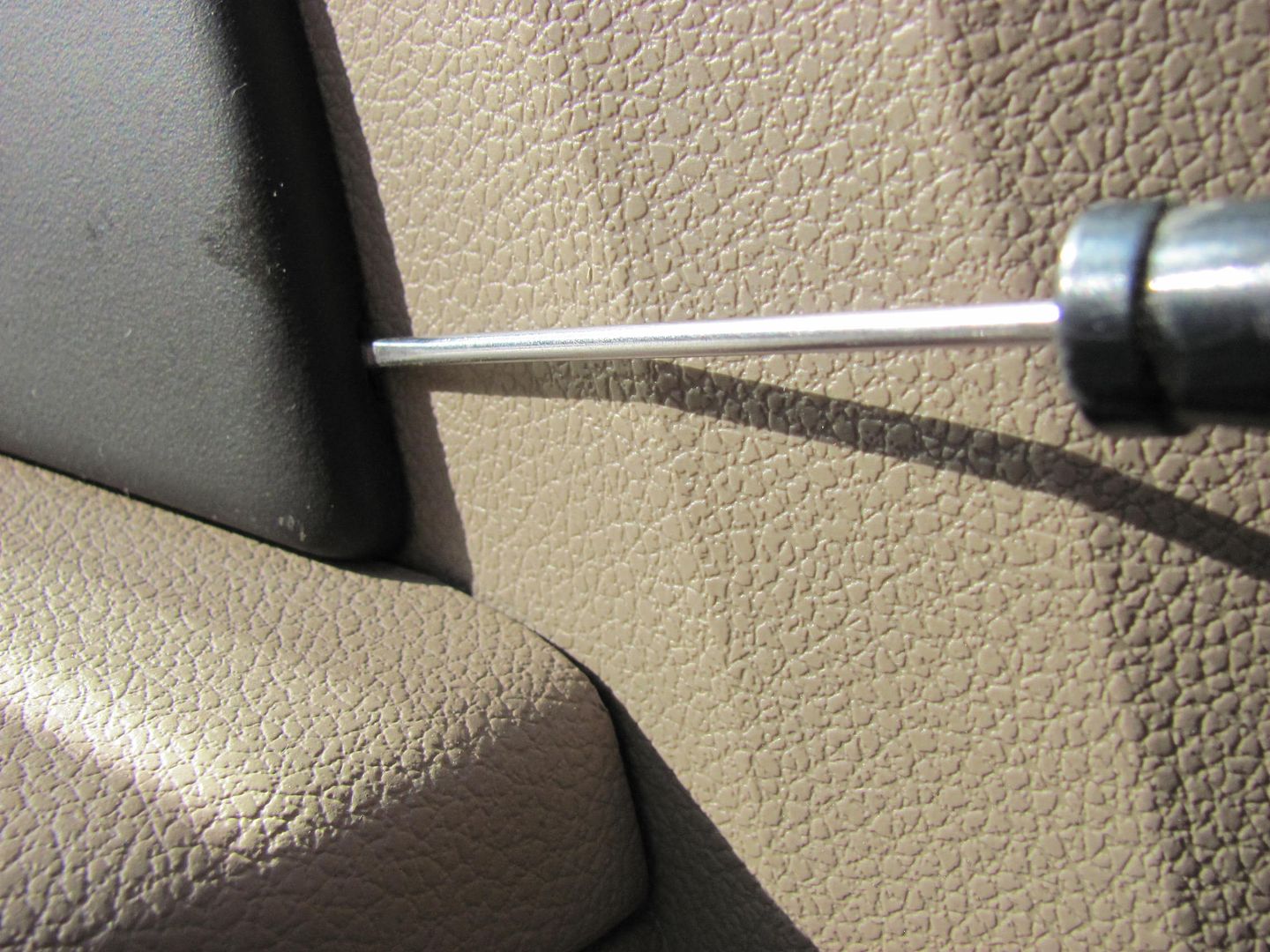
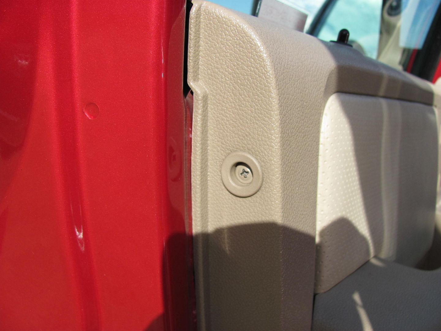
Start by removing the trim plate around the door latch. There is a small recess along the front edge for placement of small prying devices:
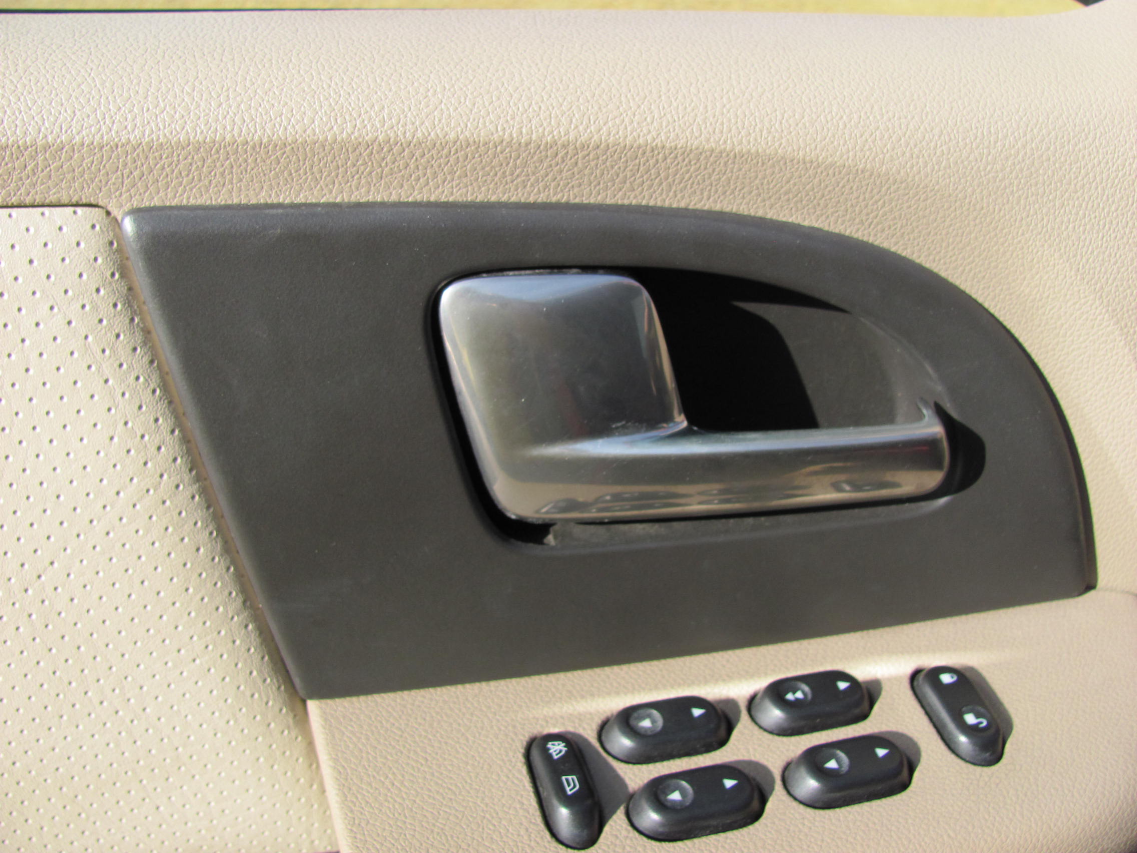


Once at this point you can easily release the remaining spring clips with gentle prying by hand. Then remove the trim plate out of the way.
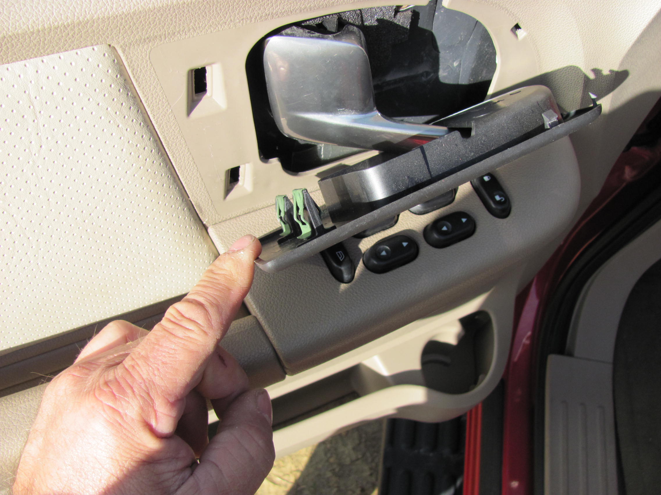
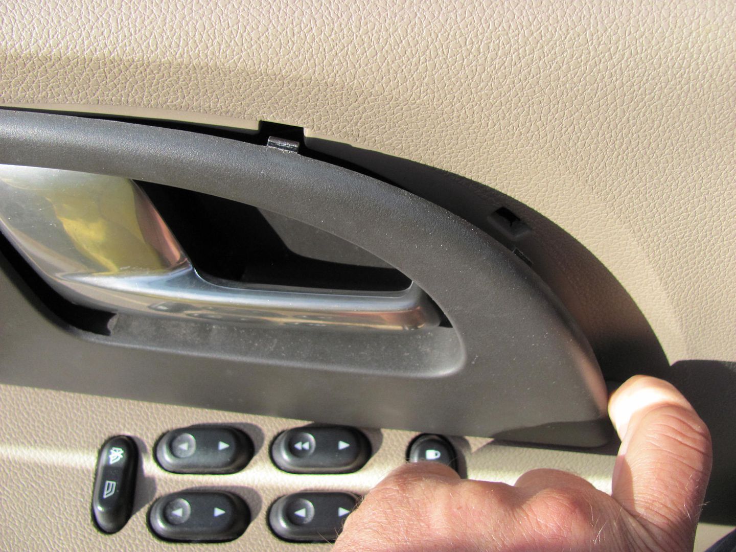
Next, to remove the switch panel, genntly pry up by hand on the front edge. These are more spring clips, and pull out fairly easy.
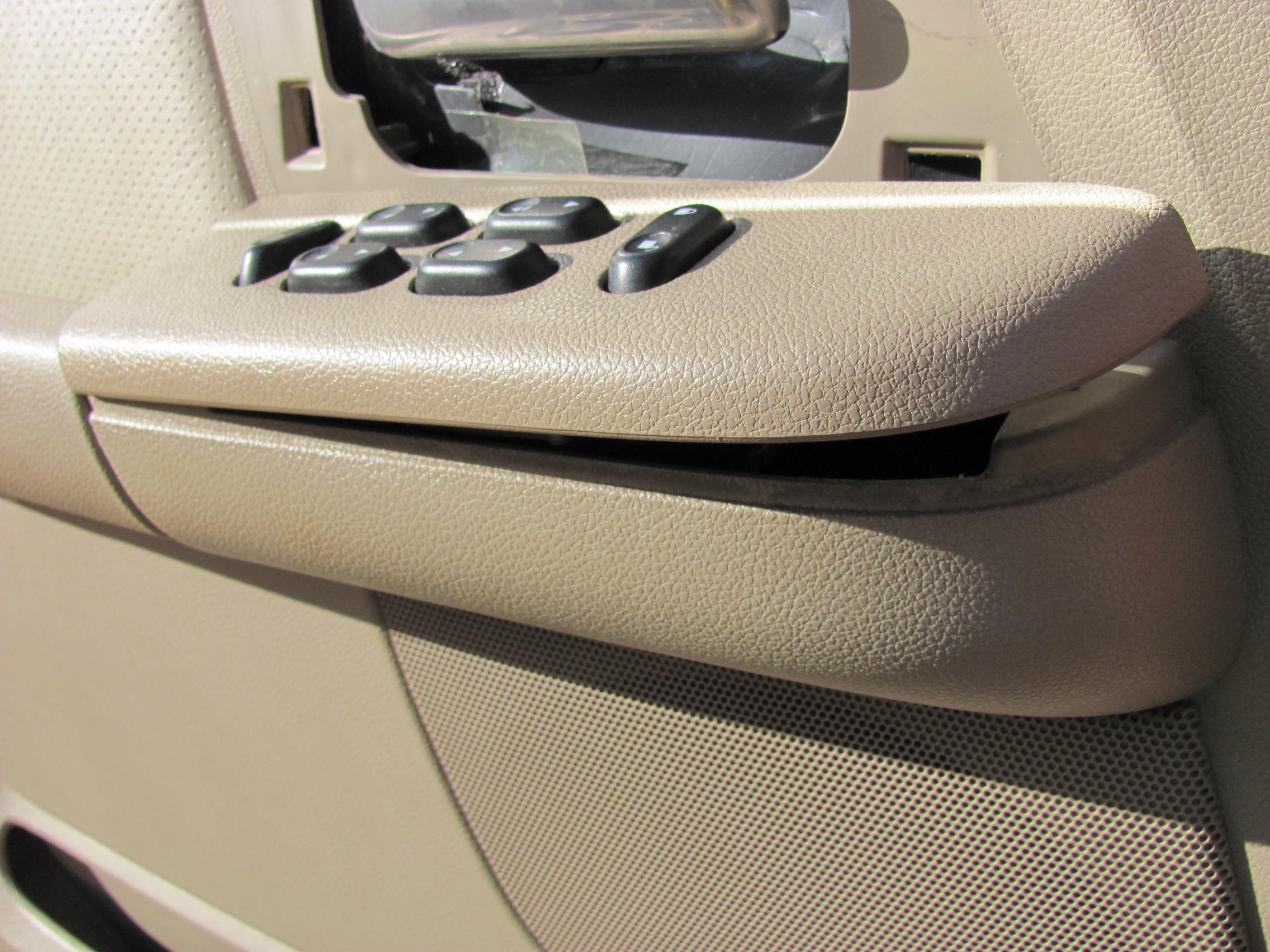
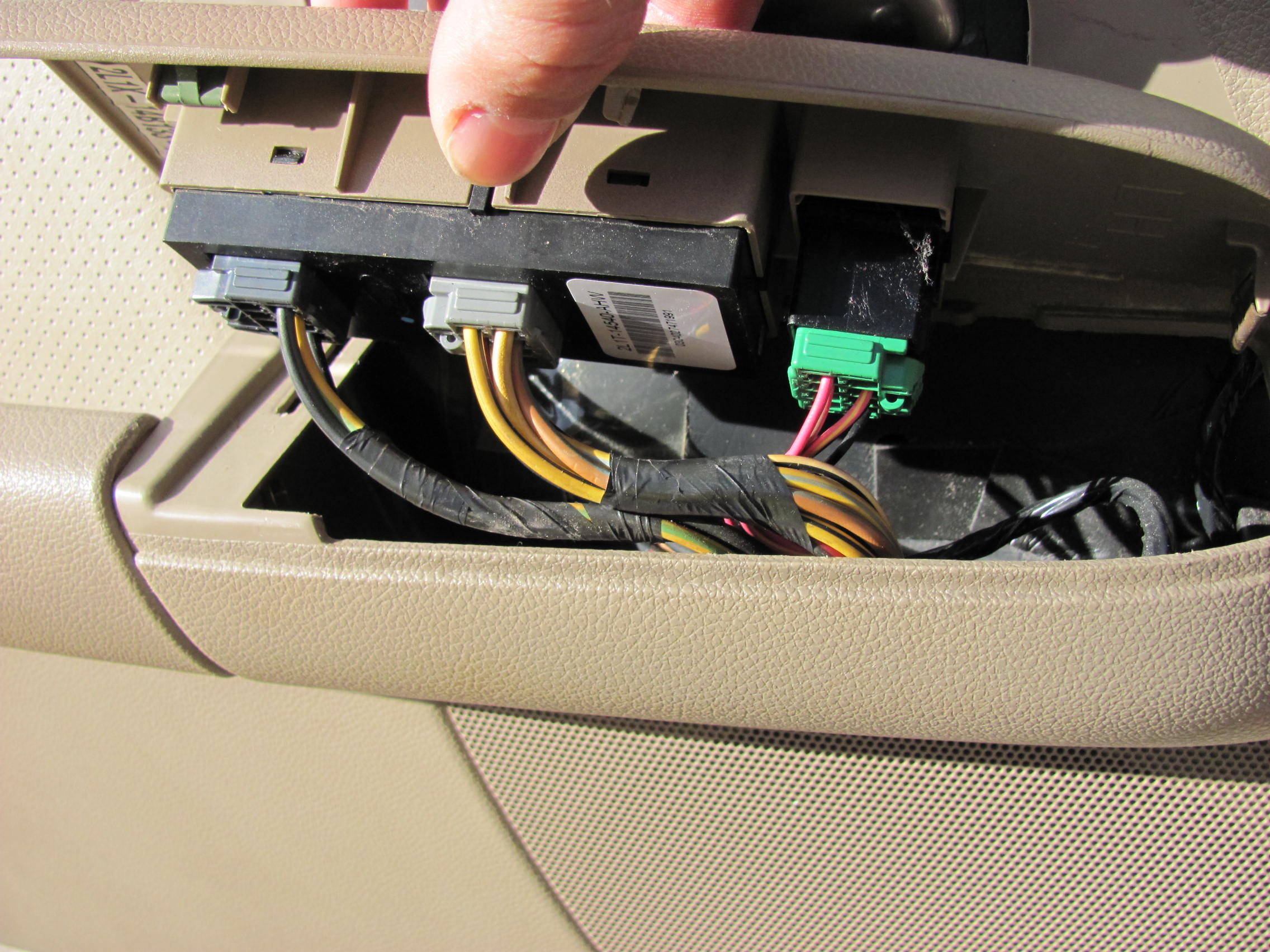
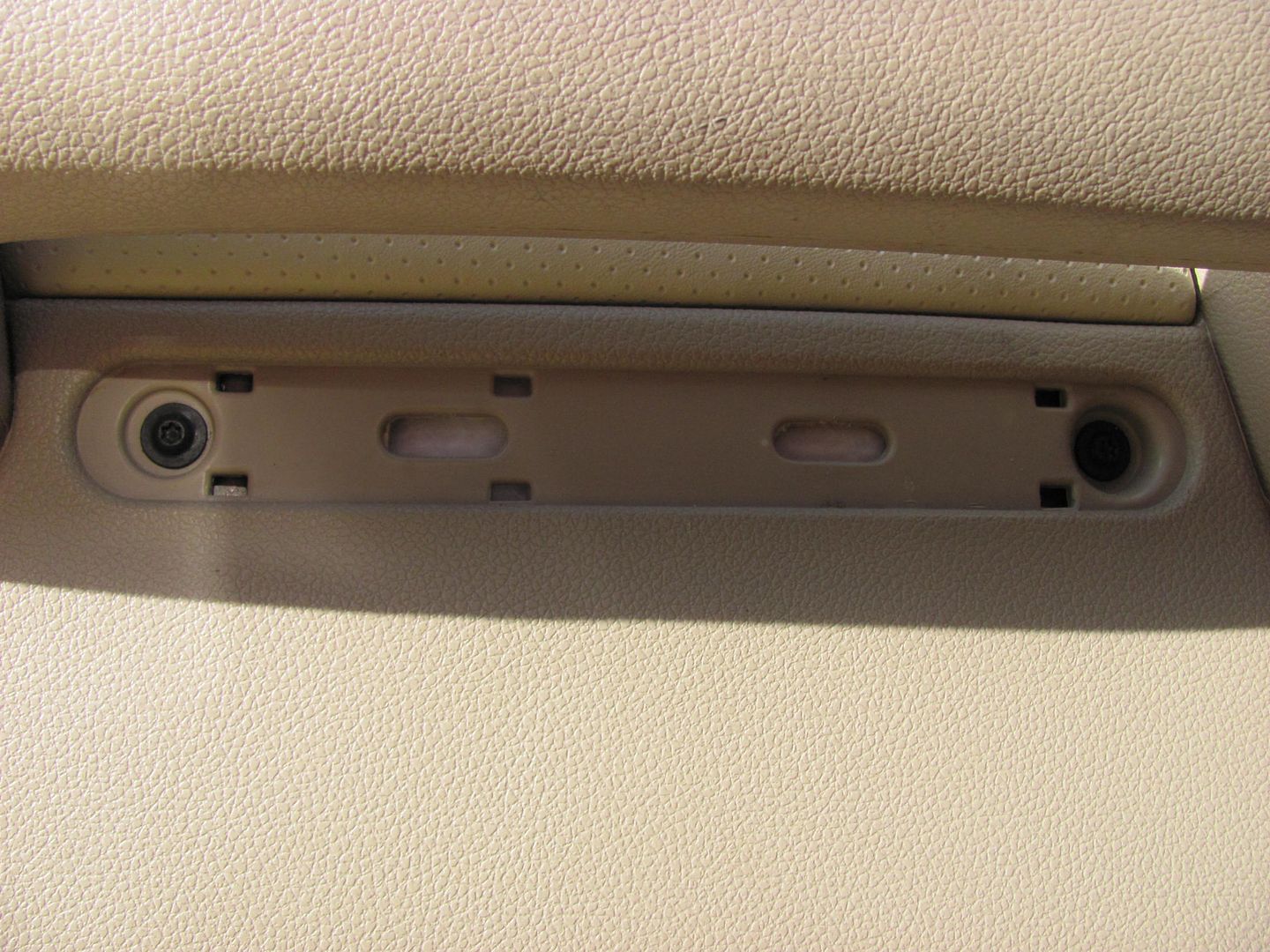
Disconnect the harness connectors and place switch panel out of the way. Beneath the door pull handle, there is a trim plate that has another recess notch along the bottom for small prying devices. This will reveal two Torx screws, T15 I believe they were.... remove parts and set aside.
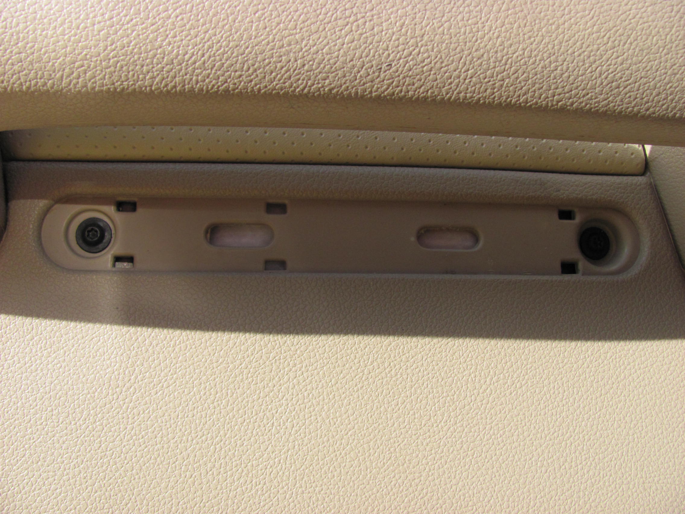
Next, remove the two hex screws at the bottom of the door panel. These are likely Metric, but my 1/4" drive six point SAE set removed them just fine..
At the top front, pull out to release the spring clip fasteners:
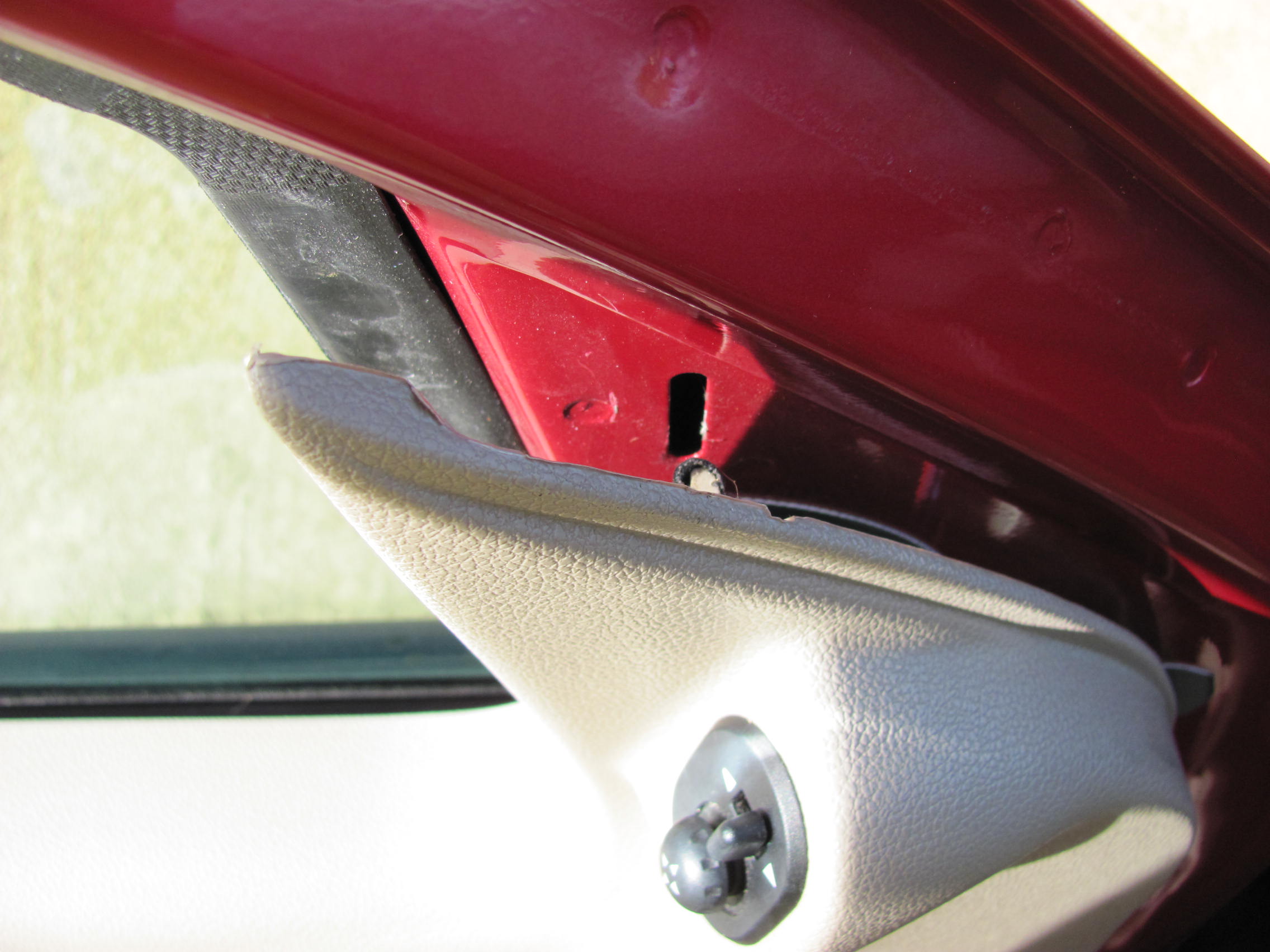
.......and when the door panel still fails to release, it's because you forgot this screw along the back edge of the door panel....
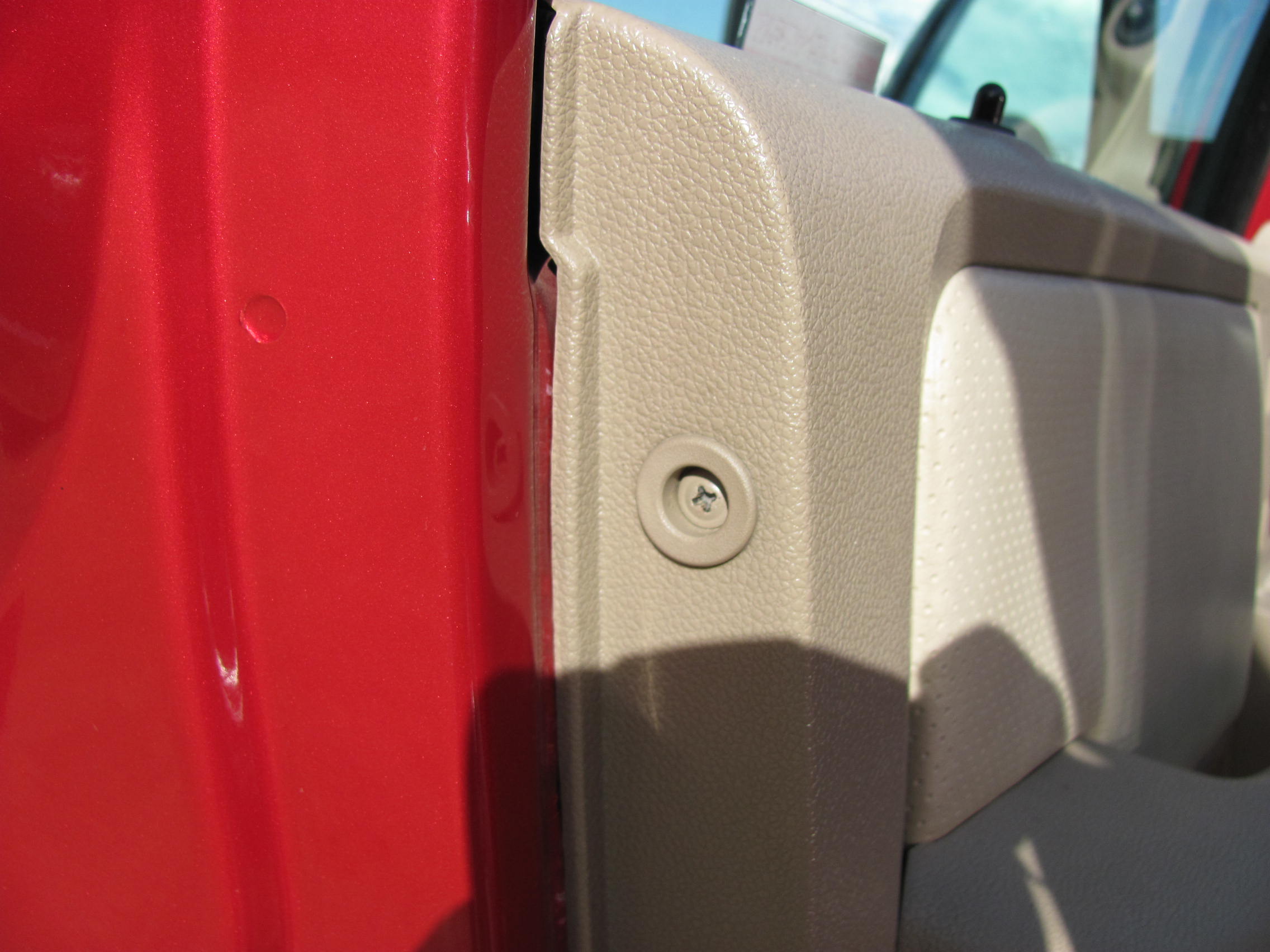
Inside of the door panels show it's a simple lift about 3/4" and pull out...
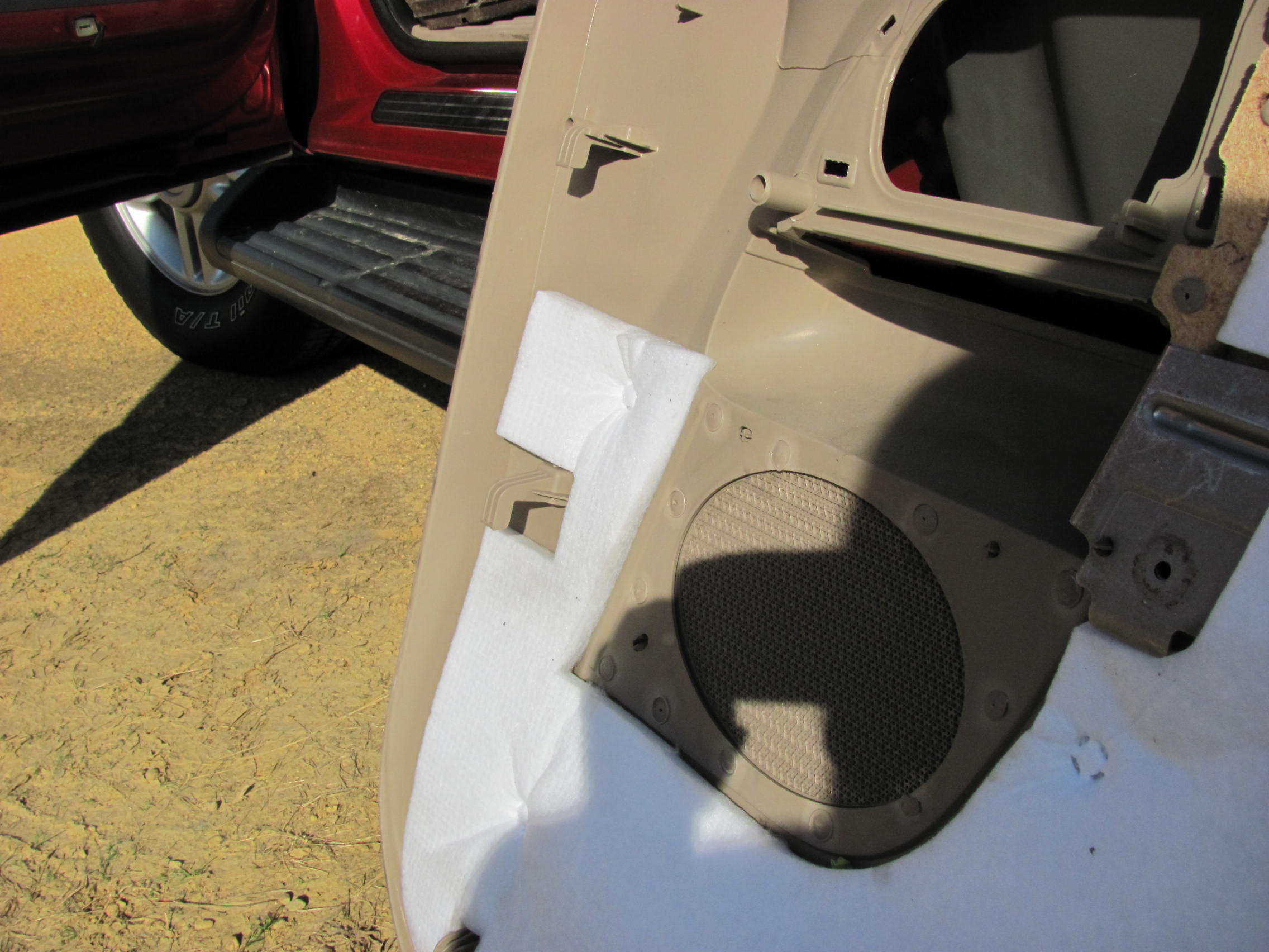
Starting at the rear of the door, gently pull the vapor barrier forward, in an attempt to keep it in one piece.
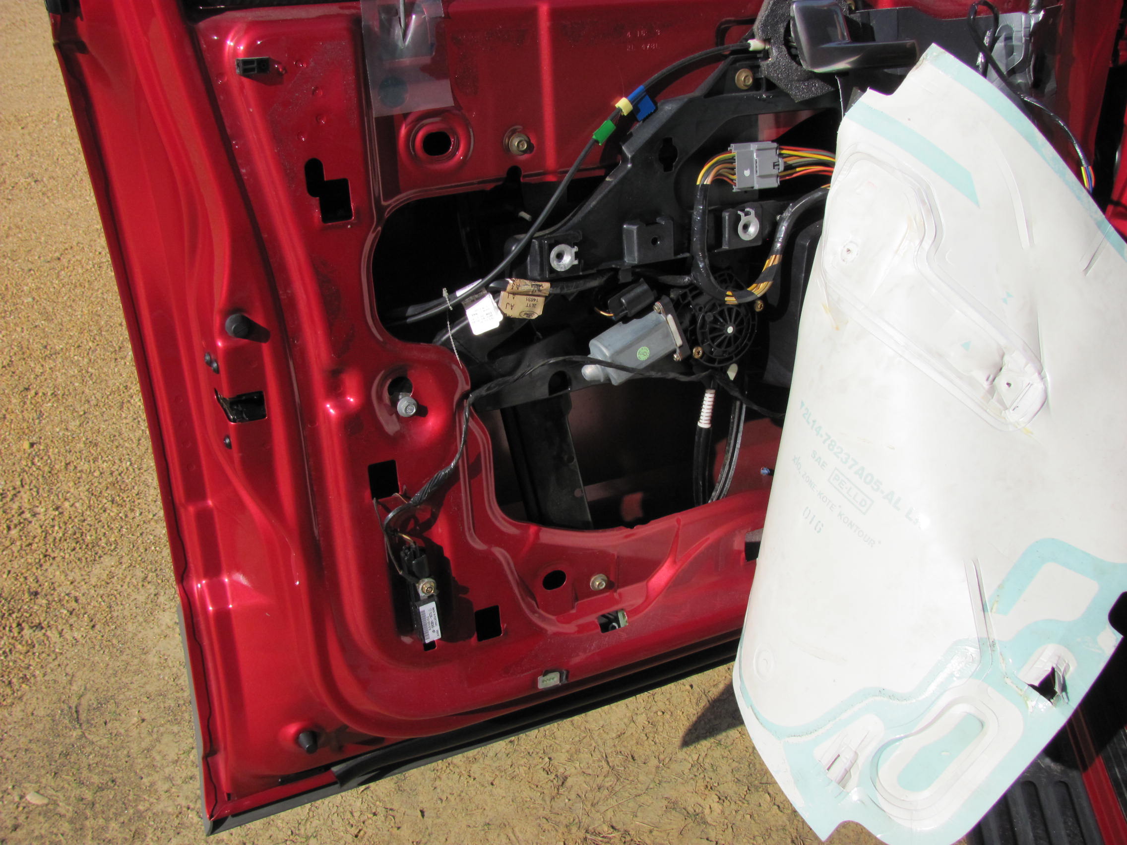
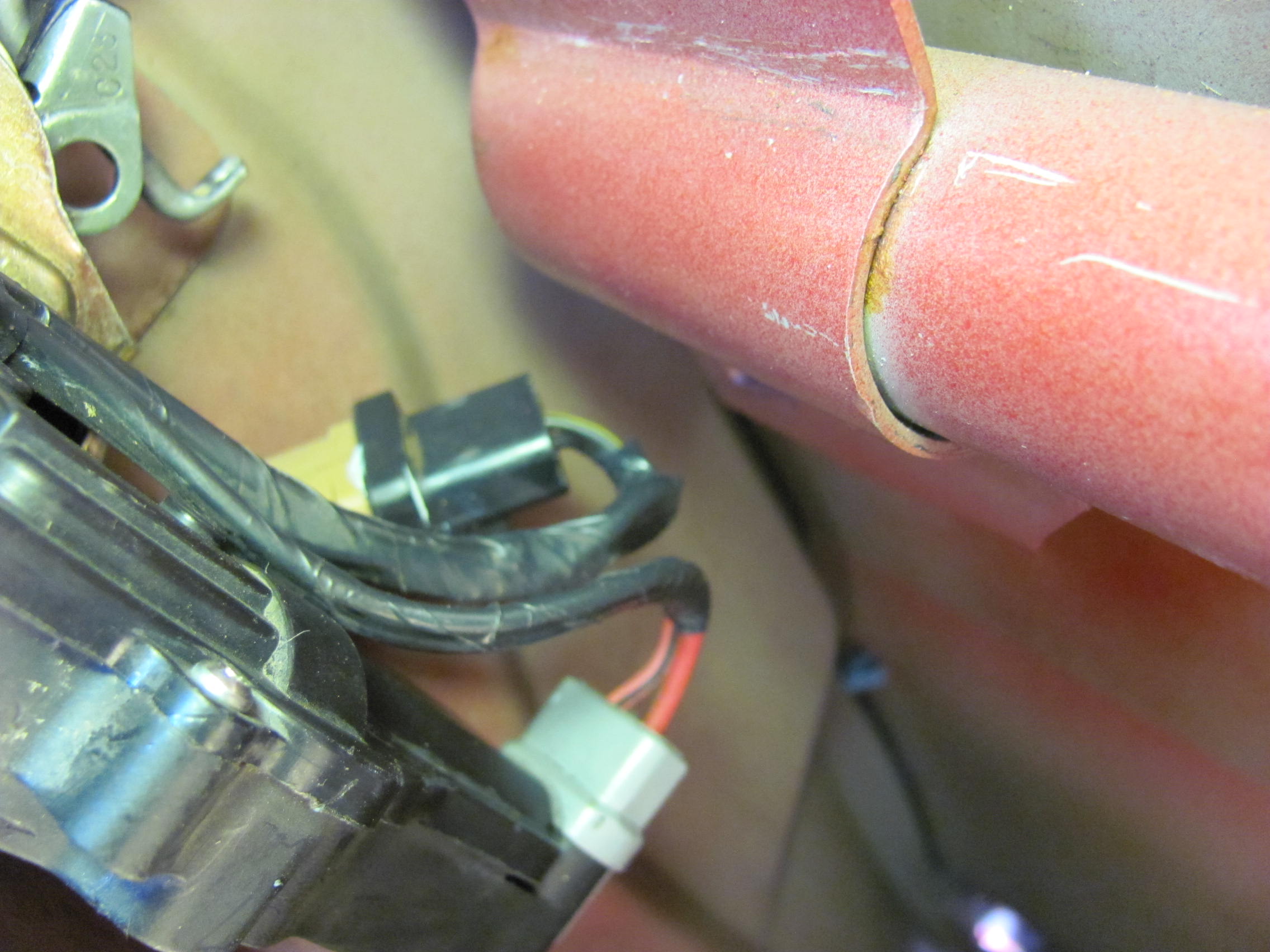
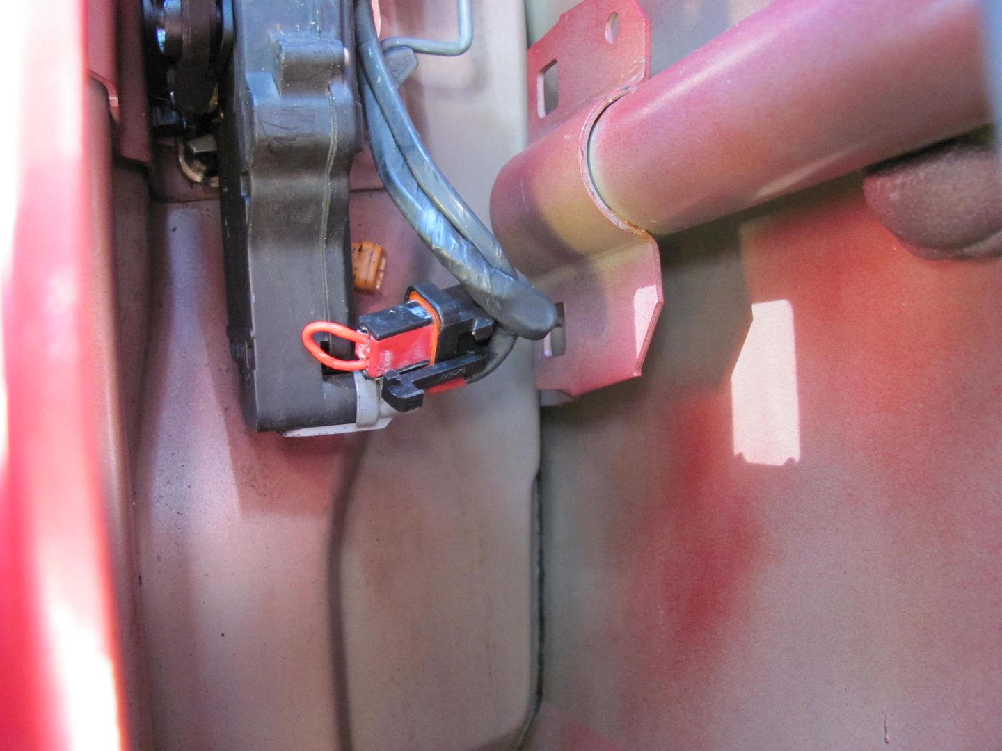
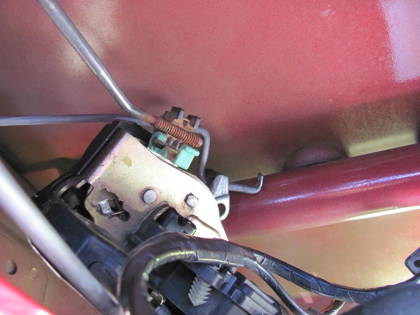
Hiding behind the door latch, the orange square item is the connector port on our culprit sensor/switch. The red jumper wire kept lights off while I awaited the parts delivery...

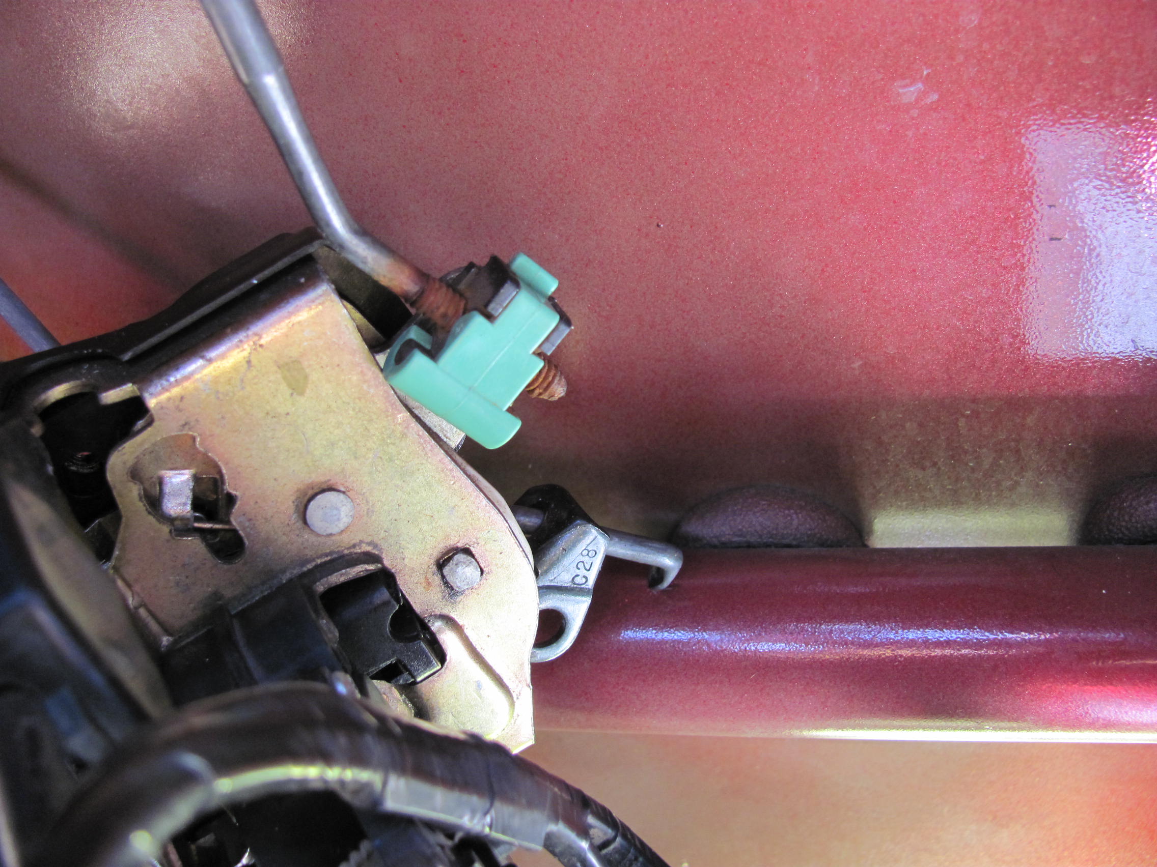
Three more torx screws will release the latch for more working room, and I found removing one end of the two latch/lock rods will also help to twist the lock assy around for better access. The lock mechanism rod can be easily released by removing the e-clip shown, and the plastic clamp (green in color) can be pried around to release the latch rod.
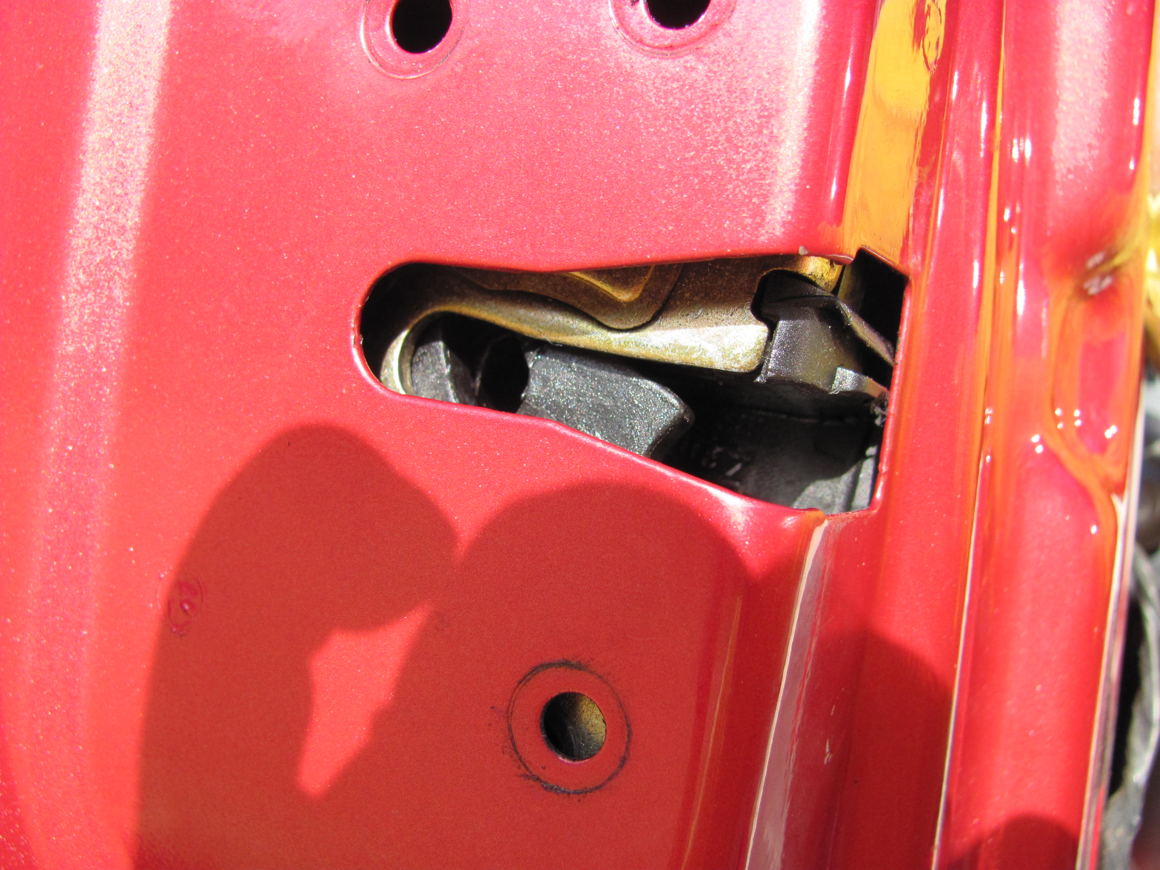


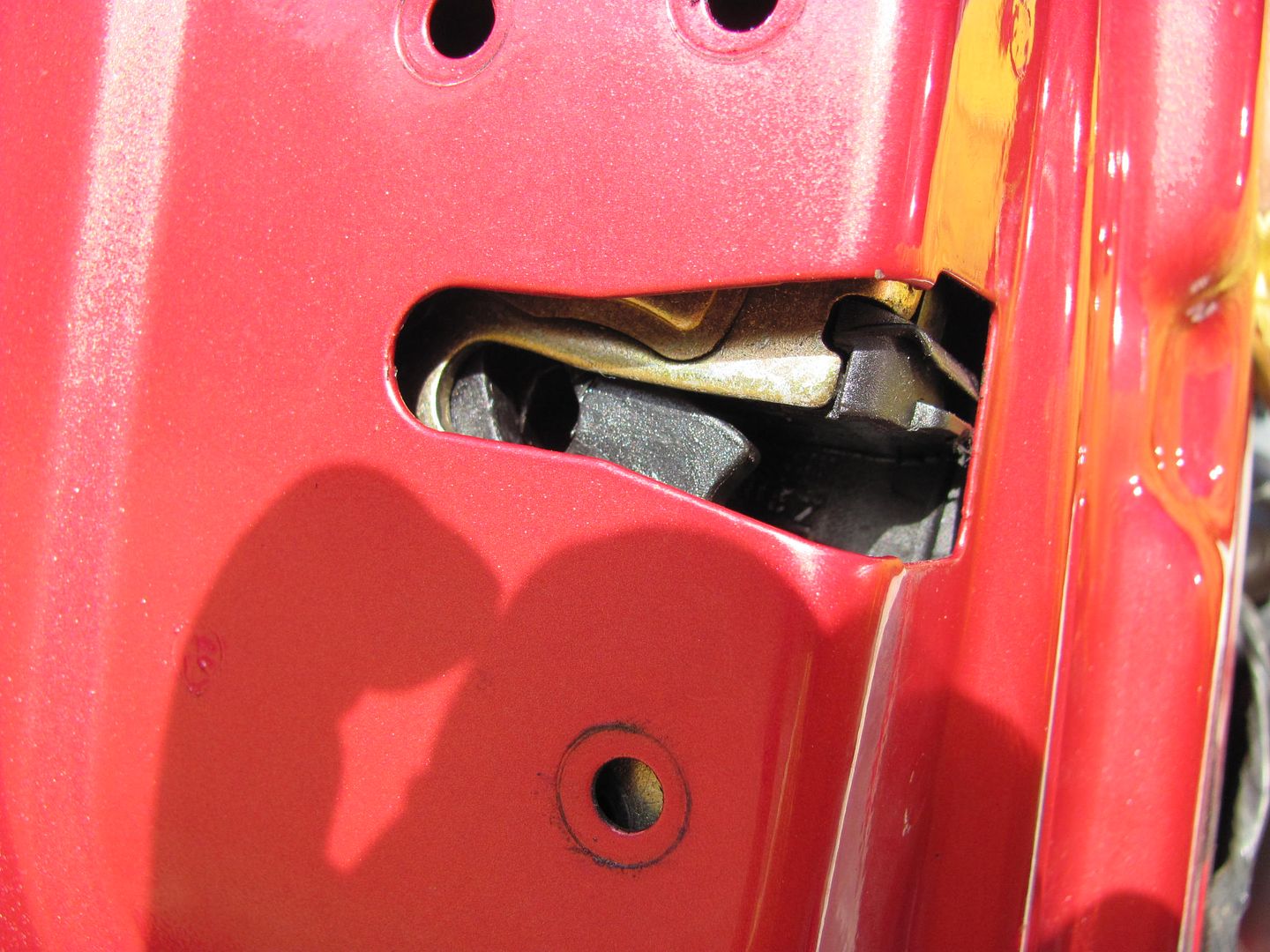
Now that we can see things, the switch is actually held in by two spring loaded tabs, the gap between them (pointed too by screwdriver) is where the keyway on the switch locks in place.
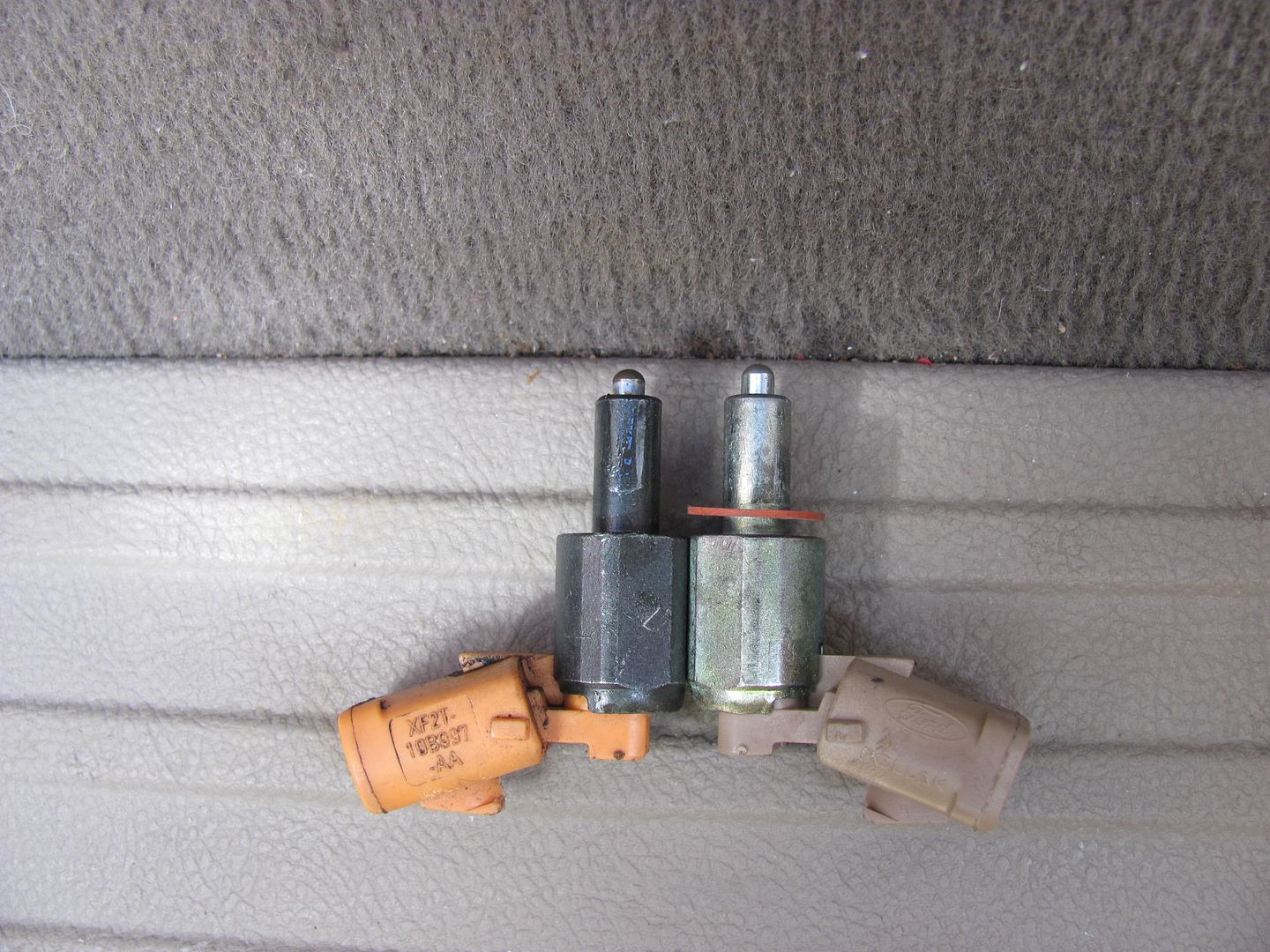
A quick 1/4 turn should release the switch. I don't know whether this is wear or product improvement, but it looks like the replacement switch has the actuator protruding out slightly farther.

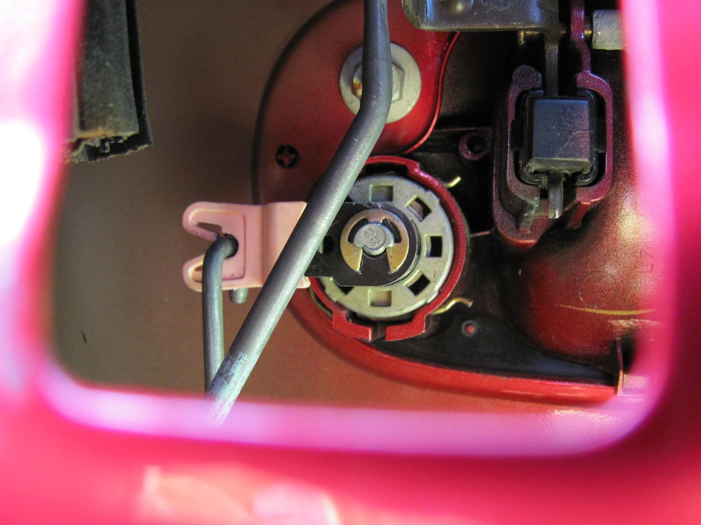
Insert new switch in hole, twist until keyway comes to rest between the two tabs, and re-assemble. All ready to turn lights on and off again:
Reverse removal process to reassemble door panel. Done.....until next time.
03 driver's door panel:
Start by removing the trim plate around the door latch. There is a small recess along the front edge for placement of small prying devices:
Once at this point you can easily release the remaining spring clips with gentle prying by hand. Then remove the trim plate out of the way.
Next, to remove the switch panel, genntly pry up by hand on the front edge. These are more spring clips, and pull out fairly easy.
Disconnect the harness connectors and place switch panel out of the way. Beneath the door pull handle, there is a trim plate that has another recess notch along the bottom for small prying devices. This will reveal two Torx screws, T15 I believe they were.... remove parts and set aside.
Next, remove the two hex screws at the bottom of the door panel. These are likely Metric, but my 1/4" drive six point SAE set removed them just fine..
At the top front, pull out to release the spring clip fasteners:
.......and when the door panel still fails to release, it's because you forgot this screw along the back edge of the door panel....
Inside of the door panels show it's a simple lift about 3/4" and pull out...
Starting at the rear of the door, gently pull the vapor barrier forward, in an attempt to keep it in one piece.
Hiding behind the door latch, the orange square item is the connector port on our culprit sensor/switch. The red jumper wire kept lights off while I awaited the parts delivery...
Three more torx screws will release the latch for more working room, and I found removing one end of the two latch/lock rods will also help to twist the lock assy around for better access. The lock mechanism rod can be easily released by removing the e-clip shown, and the plastic clamp (green in color) can be pried around to release the latch rod.
Now that we can see things, the switch is actually held in by two spring loaded tabs, the gap between them (pointed too by screwdriver) is where the keyway on the switch locks in place.
A quick 1/4 turn should release the switch. I don't know whether this is wear or product improvement, but it looks like the replacement switch has the actuator protruding out slightly farther.
Insert new switch in hole, twist until keyway comes to rest between the two tabs, and re-assemble. All ready to turn lights on and off again:
Reverse removal process to reassemble door panel. Done.....until next time.
Last edited by MP&C; Nov 3, 2010 at 10:48 AM. Reason: steel kant spel
Thread Starter
|
Tuned
Joined: Aug 2007
Posts: 458
Likes: 120
From: Maryland
As an update, I had another incident with the dreaded interior lights staying on, same truck, going on 165K miles. Had to pull up this thread to refresh my memory and try and save some time... and in the process I came up with some clarifications that may help out, so any changes to the previous post will be in Blue Text...
Now that I had done it before, and leaving the latch/lock rods alone, this was about a 15 minute job, including the test drive..
To start off, I've been through about three dousings with the WD40, which worked well....until this last time. After emptying two cans, I figured time to open up some doors. Each door was opened up, removed the door panels, disconnected the harness from the door ajar sensor switches, and install a temporary jumper to isolate the problem. In true Murphy fashion, I started at the tailgate and finished up at the drivers door, where, come to find out, the problem existed. Suggestion one would be to start your search at the drivers door, likely the culprit with the most use. I left my temporary jumper in the harness while the switch/sensor was placed on order....no one had it in stock. I would have taken pictures of the initial fiasco, but trying to work after dark and take pictures as well......it didn't happen. Once the switch came in I had a nice sunny day for replacement, so I thought to show the process for those wishing to tackle it themselves....
03 driver's door panel:

Start by removing the trim plate around the door latch. There is a small recess along the front edge for placement of small prying devices:

Once at this point you can easily release the remaining spring clips with gentle prying by hand. Then remove the trim plate out of the way.

Next, to remove the switch panel, genntly pry up by hand on the front edge. These are more spring clips, and pull out fairly easy.


Disconnect the harness connectors and place switch panel out of the way. Beneath the door pull handle, there is a trim plate that has another recess notch along the bottom for small prying devices. This will reveal two Torx screws, T15 I believe they were.... remove parts and set aside.

Next, remove the two hex screws at the bottom of the door panel. These are likely Metric, but my 1/4" drive six point SAE set removed them just fine..

At the top front, pull out to release the spring clip fasteners:

.......and when the door panel still fails to release, it's because you forgot this screw along the back edge of the door panel....
Inside of the door panels show it's a simple lift about 3/4" and pull out...

Starting at the rear of the door, gently pull the vapor barrier forward, in an attempt to keep it in one piece.

Hiding behind the door latch, the orange square item is the connector port on our culprit sensor/switch. The red jumper wire kept lights off while I awaited the parts delivery...
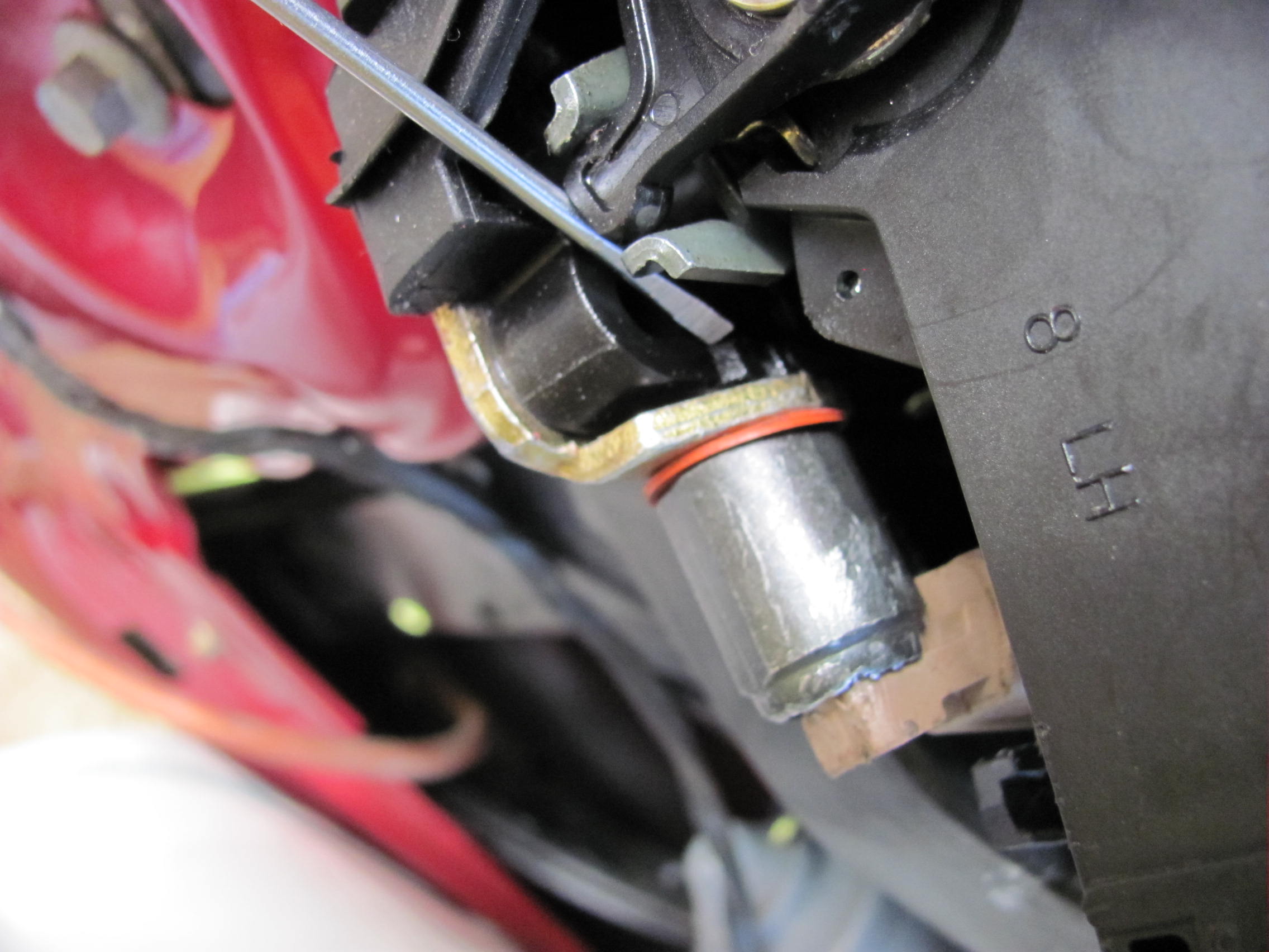
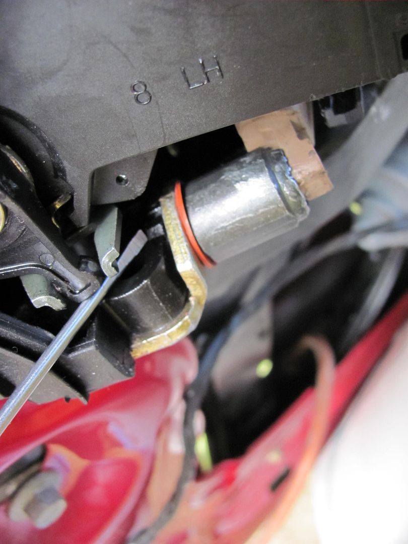
Three more torx screws (T25) will release the latch for more working room. The switch is installed vertically from the bottom, and about a 1/4 turn holds it in place. To release, push the latch slightly forward in the door to provide some room for rotation, and rotate the switch toward the jamb.. You may find this easier after the harness connector has been removed to allow easier rotation. It only takes about 1/4 turn, and pull downward.
(removed this step....and I found removing one end of the two latch/lock rods will also help to twist the lock assy around for better access. The lock mechanism rod can be easily released by removing the e-clip shown, and the plastic clamp (in color) can be pried around to release the latch rod. )

Now that we can see things, the switch is actually held in by two spring loaded tabs, the gap between them (pointed too by screwdriver) is where the keyway on the switch locks in place.
A quick 1/4 turn should release the switch. I don't know whether this is wear or product improvement, but it looks like the replacement switch has the actuator protruding out slightly farther.
Insert new switch in hole, twist until keyway comes to rest between the two tabs, and re-assemble. All ready to turn lights on and off again:

Reverse removal process to reassemble door panel. Done.....until next time.
03 driver's door panel:
Start by removing the trim plate around the door latch. There is a small recess along the front edge for placement of small prying devices:
Once at this point you can easily release the remaining spring clips with gentle prying by hand. Then remove the trim plate out of the way.
Next, to remove the switch panel, genntly pry up by hand on the front edge. These are more spring clips, and pull out fairly easy.
Disconnect the harness connectors and place switch panel out of the way. Beneath the door pull handle, there is a trim plate that has another recess notch along the bottom for small prying devices. This will reveal two Torx screws, T15 I believe they were.... remove parts and set aside.
Next, remove the two hex screws at the bottom of the door panel. These are likely Metric, but my 1/4" drive six point SAE set removed them just fine..
At the top front, pull out to release the spring clip fasteners:
.......and when the door panel still fails to release, it's because you forgot this screw along the back edge of the door panel....
Inside of the door panels show it's a simple lift about 3/4" and pull out...
Starting at the rear of the door, gently pull the vapor barrier forward, in an attempt to keep it in one piece.
Hiding behind the door latch, the orange square item is the connector port on our culprit sensor/switch. The red jumper wire kept lights off while I awaited the parts delivery...
Three more torx screws (T25) will release the latch for more working room. The switch is installed vertically from the bottom, and about a 1/4 turn holds it in place. To release, push the latch slightly forward in the door to provide some room for rotation, and rotate the switch toward the jamb.. You may find this easier after the harness connector has been removed to allow easier rotation. It only takes about 1/4 turn, and pull downward.
(removed this step....and I found removing one end of the two latch/lock rods will also help to twist the lock assy around for better access. The lock mechanism rod can be easily released by removing the e-clip shown, and the plastic clamp (in color) can be pried around to release the latch rod. )
Now that we can see things, the switch is actually held in by two spring loaded tabs, the gap between them (pointed too by screwdriver) is where the keyway on the switch locks in place.
A quick 1/4 turn should release the switch. I don't know whether this is wear or product improvement, but it looks like the replacement switch has the actuator protruding out slightly farther.
Insert new switch in hole, twist until keyway comes to rest between the two tabs, and re-assemble. All ready to turn lights on and off again:
Reverse removal process to reassemble door panel. Done.....until next time.
Now that I had done it before, and leaving the latch/lock rods alone, this was about a 15 minute job, including the test drive..

New User
Joined: Jun 2013
Posts: 1
Likes: 0
Like Wow!
Just incredible pics and explanations on this bugger of a problem. I had the panel off (easy enough), but getting to the sensor is well, another story. We had 100 of photocells, microswitches and sensors and my Anheuser plant, I don't think I've seen a design as poor as this, both in terms of access and longevity.
My greatest thanks for your excellent work here
Bob R.
My greatest thanks for your excellent work here
Bob R.
Trending Topics
Cargo Master
Joined: Jan 2011
Posts: 2,023
Likes: 1
From: New Castle, Delaware
This is good to know. More then likely it is in the same place as my 98. I also got feed up with WD40 mess. I ended up just removing the fuse from the inside fuse box under the driver dish. Lights still work manually but that's about it. Thanks for this awesome write-up I know what I'm in for. I
FTE Stories
Ford Trucks for Ford Truck Enthusiasts

Rezvani's Latest Post-Apocalytic Monster Is a Ford F-150 Raptor Underneath
Verdad Gallardo
Top 10 Most Expensive Ford Trucks Ever Sold on Bring a Trailer
Joe Kucinski
2027 Ford Super Duty Buyer's Guide (Every Model, Engine, & Package)
Brett Foote
Top 10 Ford Truck Tragedies
Joe Kucinski
AEV FXL Super Duty - the Super Duty Raptor Ford Doesn't Make
Brett Foote
Lobo Vs Lobo: Proof the F-150 Lobo Should Be Even Lower!
Michael S. Palmer
Ford's 2001 Explorer Sportsman Concept Looks For a New Home
Verdad Gallardo
10 Best Ford Truck Engines We Miss the Most!
Joe Kucinski
2026 Shelby F-150 Off-Road: Better Than a Raptor R?
Brett Foote
New User
Joined: Oct 2010
Posts: 2
Likes: 0
Great write-up! I have a 2002 F-150. I saw so many conflicting reports about which driver's side door ajar switch was right for my truck, that I decided to remove the "bad" switch before I bought a replacement. (Symptoms: Driver's side door never registered as open...no dome light, no chime...unless I stick my finger in the door latch with the door open and press down a little bit. i.e. switch is stuck open or worn so much that it no longer closes.)
After pulling out the switch (p/n XF1T-10B997-AA) I noticed there was about 1/16th inch "play" compressing the plastic half of the switch towards the metal half. I buzzed out the operation of the switch and determined that fully seating the plastic portion of the switch would cause the switch to close with less actuator movement. I bent the lip of metal holding the plastic portion of the switch in three spots using a hammer and punch in order to fully seat it, thus reducing the amount of actuator movement required to close the switch...the door ajar functionality works fine now!
The switch actuator and door latch did not look very worn, surprising given the 14 years of use. My guess is that this switch was constructed with too much play between the plastic and metal portions of the switch, or 14 years of door use took a toll on the lip of metal keeping the plastic portion of the switch fully seated in the metal portion.
Enjoy!

5th Wheeling
Joined: Aug 2001
Posts: 48
Likes: 0
I just replaced an 03 Expedition R side front door ajar switch with a Standard motor products(DS957).I had to unscrew the (3) Jamb screws to get my arm far enough in to bust it loose.Mine was pretty snug.I did not loosen the rods.The ball end was quite stuck in.Seems to work fine.

Fleet Mechanic
Joined: Feb 2011
Posts: 1,812
Likes: 88
From: Thousand Oaks, CA
... After pulling out the switch (p/n XF1T-10B997-AA) I noticed there was about 1/16th inch "play" compressing the plastic half of the switch towards the metal half.... I bent the lip of metal holding the plastic portion of the switch in three spots using a hammer and punch in order to fully seat it, thus reducing the amount of actuator movement required to close the switch...the door ajar functionality works fine now! ...
The left-front door switch is a Ford XF2T-10B997-AA or Motorcraft SW5854.
The right-rear door switch is a Ford XF2T-14018-AA or Motorcraft SW5429B.
The difference between them is the position of a nub on the metal half that locks into the latch assembly.
The switch is normally closed and opens when the plunger is depressed.
There are a lot of different numbers for these switches which is really annoying.
The above switches are in our 2003 Expedition and also used in 2002-2003 Excursion, but not the years on either side according to the Amazon fitment guide.
There is a procedure in another thread that worked great for locating our bad switch.
Start the car, turn on the headlights, turn on the dash/interior lights with the roller wheel on the right end of the headlight switch panel and drive 50-100ft. The interior lights should go out after 30 sec. Pull over, select Park and leave the engine running. Open/close the doors/rear hatches one-by-one. After each one is opened/closed the interior lights will come on and go out after a couple of seconds. The door with a bad switch will not turn the interior lights on.


Thread
Thread Starter
Forum
Replies
Last Post
bigblockford_390
1999 - 2016 Super Duty
28
Sep 17, 2016 07:47 PM