1966 F100 2WD 352/3 Speed Clutch Assembly Help?
#1
 05-09-2013, 01:18 PM

1966 F100 2WD 352/3 Speed Clutch Assembly Help?
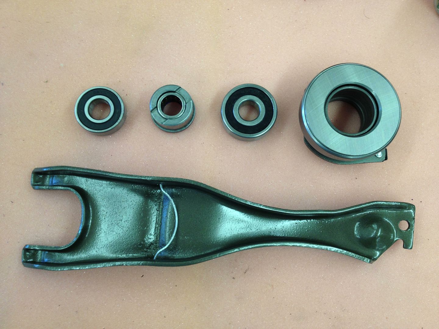
I have a bunch of parts and no idea how they go together on the '66 F100 we are restoring. It had a 302 in it when we got it so none of the 352/3 speed parts we have have been together before- nothing to go by.
Here are the parts I have. I've found a couple vague diagrams by googling but none of them show the two bearing that were in the clutch kit; only one.
Here are the parts I have. I've found a couple vague diagrams by googling but none of them show the two bearing that were in the clutch kit; only one.


#2
05-09-2013, 01:49 PM


I have a bunch of parts and no idea how they go together on the '66 F100 we are restoring. It had a 302 in it when we got it so none of the 352/3 speed parts we have have been together before- nothing to go by.
Here are the parts I have. I've found a couple vague diagrams by googling but none of them show the two bearing that were in the clutch kit; only one.
Here are the parts I have. I've found a couple vague diagrams by googling but none of them show the two bearing that were in the clutch kit; only one.
Original pilot bearing was made of bronze. 1971: Ford replaced it with a sealed bearing.
#4
05-09-2013, 06:17 PM

Postmaster
one other thing to check..the FE engines used 2 different pressure plates...390s stand alone which is what most parts houses stock...most...including I until a few weeks ago, thought all FE flywheels/pressure plates are the same...they arent!!!
The 352/360 is one application and 390 is another...LUK REGARDLESS of what their parts catalog says DO NOT STOCK THE 352/360 SETUP!
I cant speak to other suppliers but the one...measure the bolt distance from ear to ear as its vastly different when you try to put a 390 on the smaller engines flywheel...the clutch disc I as I recall is different as well...diameter if Im not mistaken...
- cs65
#5
05-10-2013, 04:08 AM
One other thing to check...the FE engines used 2 different clutch discs and pressure plates, 390s stand alone which is what most parts houses stock.
Until a few weeks ago, I thought all FE flywheels/clutch discs/pressure plates are the same...they arent!
The 352/360 is one application and 390 is another.
Until a few weeks ago, I thought all FE flywheels/clutch discs/pressure plates are the same...they arent!
The 352/360 is one application and 390 is another.
C5AZ-6375-K .. Flywheel-Use with 11" clutch / (6) 5/16" -18 pressure plate attaching holes on a 12 3/8" bolt circle.
1965/67 F100/350 & Galaxie/LTD 352 / 1968/76 F100/350 360.
------------------------------------------------------------------------
C5AZ-6375-L .. Flywheel-Use with 11 1/2" clutch / (6) 5/16" -18 pressure plate attaching holes on a 12 7/8" bolt circle.
1965/71 Galaxie/LTD 390 / 1968/76 F100/350 390.
Don: This is...at least...the 500th time I posted this 1965/76 F100/350 FE flywheel/clutch info on FTE!
#6
05-13-2013, 09:44 AM
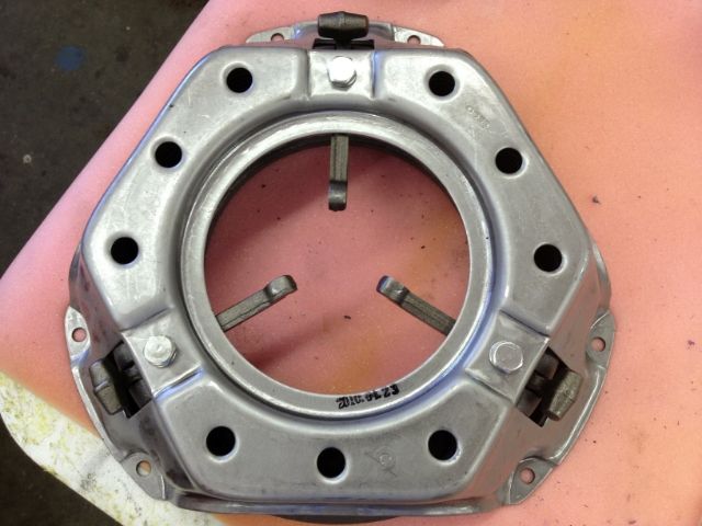
I checked the fit of the pressure plate and it's the correct one.
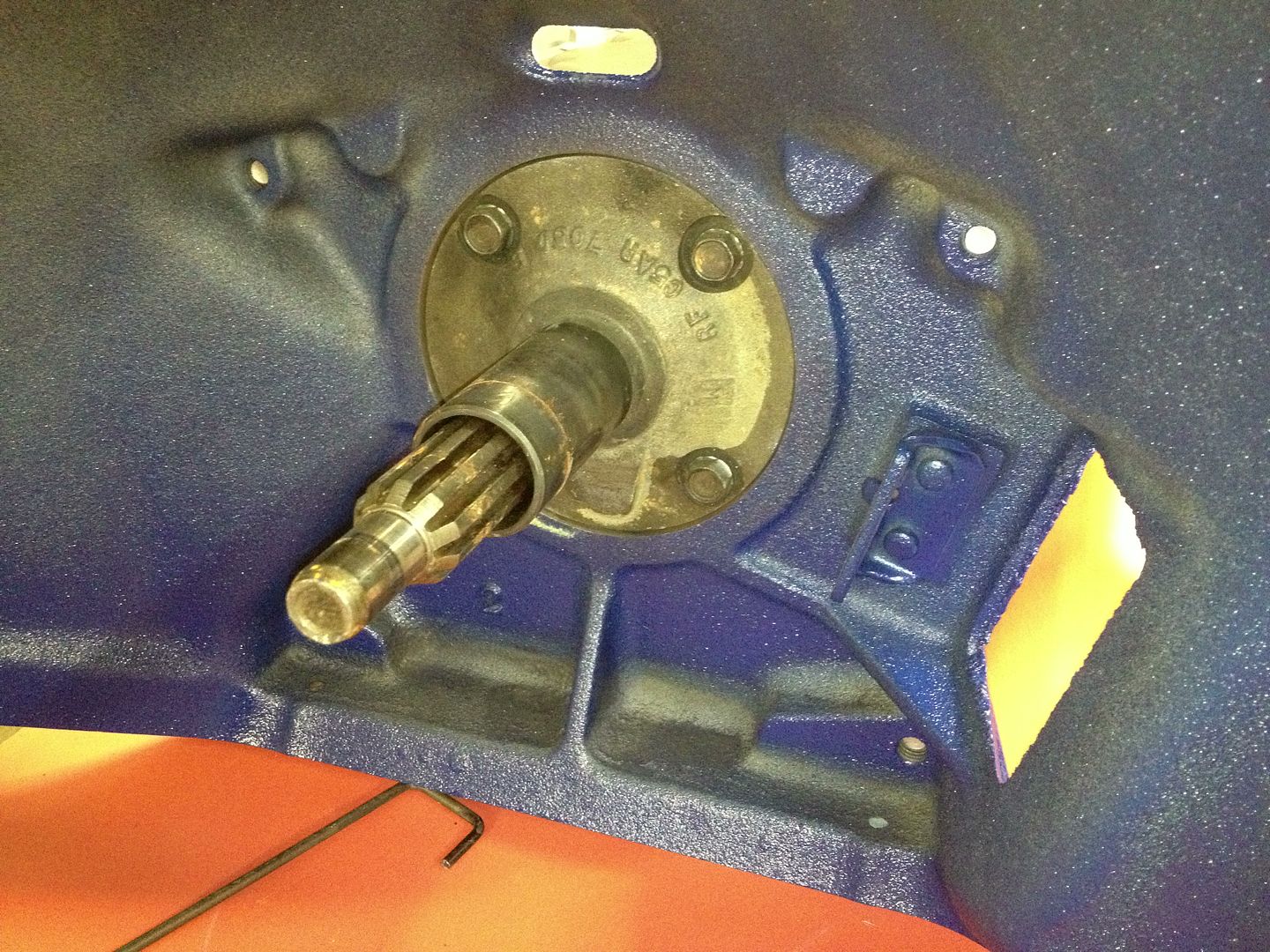
I just pulled the engine off the stand so I could get a good look at the pilot bearing. It's solid steel, is there any need to replace it with the sealed bearing or can I polish the bore with fine sandpaper (800-1500 grit), add a little grease, and leave it be?
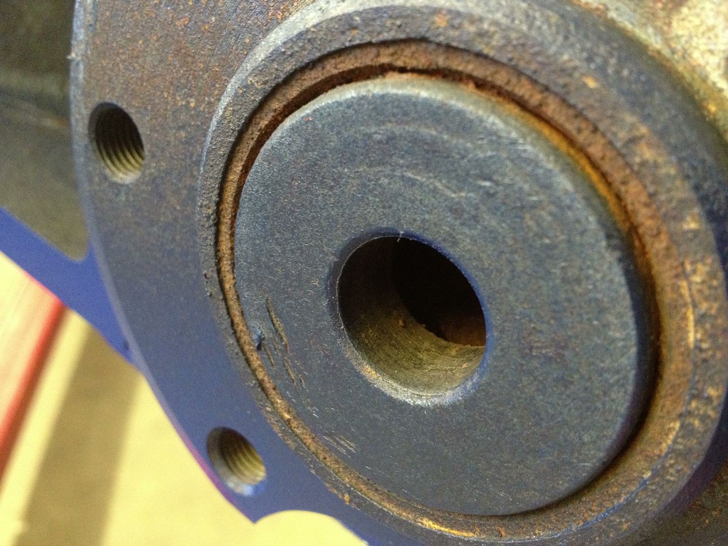
I just pulled the engine off the stand so I could get a good look at the pilot bearing. It's solid steel, is there any need to replace it with the sealed bearing or can I polish the bore with fine sandpaper (800-1500 grit), add a little grease, and leave it be?

#7
05-13-2013, 01:48 PM

I checked the fit of the pressure plate and it's the correct one.
I just pulled the engine off the stand so I could get a good look at the pilot bearing. It's solid steel, is there any need to replace it with the sealed bearing or can I polish the bore with fine sandpaper (800-1500 grit), add a little grease, and leave it be?
I just pulled the engine off the stand so I could get a good look at the pilot bearing. It's solid steel, is there any need to replace it with the sealed bearing or can I polish the bore with fine sandpaper (800-1500 grit), add a little grease, and leave it be?
When going back in, I suggest you mount the bell housing first with the 10 Oclock bolt in it, also use two jacks, one on the engine to lift it back into flat allignment as it has most likely dropped down a bit.
Good luck.
Trending Topics
#8
04-24-2017, 10:14 AM
Junior User
Join Date: Apr 2017
Location: Salt Lake City, UT
Posts: 70
Likes: 0
Received 0 Likes
on
0 Posts
Resurrecting this old post...
I have the same parts from presumably the same kit. I have determined that the bearing I need is the larger one on the far right as that's the most similar to the old bearing and is the only one that will fit the input shaft. The problem is that I didn't see how it came apart as it all just fell out when the tranny came loose.
So my questions are these: How does that bearing sit relative to the other parts? Does the flat side face the transmission with the springs against the spring arm? Do the springs clip to the spring arm? Do the springs face the transmission? Do I fit it against the spring arm before I mount the tranny or do I put it on the input shaft and line it up when I put the tranny in?
The diagram that was posted is helpful but doesn't give me that level of detail.
Any photos/descriptions will be helpful. Thanks in advance.
-Paul
#9
04-24-2017, 11:00 AM
The clips on the bearing hook onto the arm at the inner end. There's really only one way it will go. Line the lowest portion of the clips with the wells in the ends of the arms.
You'll want to clip the bearing in place before you try to install the transmission.
The flat side of the TO bearing goes against the clutch release fingers.
Chad
.
You'll want to clip the bearing in place before you try to install the transmission.
The flat side of the TO bearing goes against the clutch release fingers.
Chad
.
#10
04-24-2017, 11:13 AM
Junior User
Join Date: Apr 2017
Location: Salt Lake City, UT
Posts: 70
Likes: 0
Received 0 Likes
on
0 Posts
#12
04-24-2017, 11:28 AM
Junior User
Join Date: Apr 2017
Location: Salt Lake City, UT
Posts: 70
Likes: 0
Received 0 Likes
on
0 Posts
#13
04-24-2017, 01:54 PM
They appear to be various sizes of pilot bearings/bushings. Those go in the back end of the crankshaft to support the tip of the input shaft. One of them might be correct, you'll have to see if any are the right size for a combination of the crankshaft back end and transmission input shaft tip.
Chad
.
Chad
.
#14
04-24-2017, 02:13 PM
Junior User
Join Date: Apr 2017
Location: Salt Lake City, UT
Posts: 70
Likes: 0
Received 0 Likes
on
0 Posts

Thread
Thread Starter
Forum
Replies
Last Post
stone_cold_jo
1961 - 1966 F-100 & Larger F-Series Trucks
2
01-01-2019 04:18 AM
ggadwa
1961 - 1966 F-100 & Larger F-Series Trucks
5
09-08-2013 05:37 PM
camperspecial65
1961 - 1966 F-100 & Larger F-Series Trucks
2
02-05-2013 08:47 AM
crazed87bronco
1961 - 1966 F-100 & Larger F-Series Trucks
31
01-08-2012 12:27 PM
68ranger704
1967 - 1972 F-100 & Larger F-Series Trucks
4
05-25-2011 09:16 PM