





Just bought 06 F350 FX4 6.0!! :D

Thread Starter
|
Senior User
Joined: Apr 2011
Posts: 128
Likes: 0
From: Lancaster PA
Just bought 06 F350 FX4 6.0!! :D
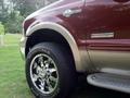
Well Just bought a 2006 F350 FX4 Lariat 6.0 PSD! Cant wait to pick it up Thursday or Friday! It has just under 30,000 miles!!! What bulletproof kit do you recommend? 
Thanks
Ron!

Thanks
Ron!

Junior User
Joined: Jun 2012
Posts: 66
Likes: 0
I just bought an 07 PSD FX4 off my father a few months ago. I too had been looking at the kits out there and had found a whole bunch of videos on youtube from this place. POWERSTROKEHELP.COM - The Information Source for Ford Power Stroke Diesel Owners & Mechanics and Home of EDAS® "Engine Damage Avoidance System" for Powerstroke Diesel Trucks I know nothing about this place but has a lot of good points about the different years of the 6.0L and 7.3L PSD's and they are in Buford GA close to my fathers house and my old stomping grounds. 06 and 07 were about the most refined years for the Ford version of the 6.0L but there are still a few items on the list for just everyday use that seem like they need some attention to avoid having problems with towing mild loads and still trying to reach 200K miles with out worries.
I am subscribing to this thread as well so I can learn more. good luck with it, good looking truck.
I am subscribing to this thread as well so I can learn more. good luck with it, good looking truck.
Elder User
Joined: Jan 2004
Posts: 900
Likes: 0
From: Arizona
I will tell you this, You wont be disappointed in my advice.

Welcome, and great looking truck.

Hotshot


Joined: Aug 2006
Posts: 17,398
Likes: 317
From: Whittier, CA
I would recommend you have BulletProofDiesel - Darn-Near Bullet Proof Diesel Products for your 6.0 before you even start watching that other guys videos.
I will tell you this, You wont be disappointed in my advice.
Welcome, and great looking truck.
I will tell you this, You wont be disappointed in my advice.
Welcome, and great looking truck.
As far as bulletproofing, at only 30k miles I think you have a long time before you should even start thinking about mods and repairs. Just spend some quality time studying the 6.0 diesel forum here, while you are enjoying your truck, and learning all you can. Don't let it all get you too scared. Once you are educated, the truck will tell you when it is time for some upgrades.
Having said that, I would start with a coolant flush, which you do yourself following the instructions found here at FTE, and install a coolant filter. Simple and inexpensive preventive addition.
Token Redneck
Joined: Jun 2007
Posts: 9,335
Likes: 344
From: Breckenridge, TX

Maintenance Checklist for a "New to Me" 6.0L Diesel:
Stage 1: Full maintenance workup
5W40 synthetic oil, with a motorcraft/racor filter and a factory oil filter cap <<< cannot stress enough checking the oil cap immediately, incorrect cap and filter combo can damage your high pressure oil system
Fuel filters (Racor or Motorcraft brand)
Coolant exchange (also install high idle mod, recommend a Cat EC-1 rated ELC coolant)
Trans fluid drain/fill and external filter
Drain water separator
Replace the air filter (Donaldson or Motorcraft filter with blue media)
Clean EGR valve
Load test batteries, replace if fail
If it's not there already, find a way to put the stock air filter back in it
Getting the baseline taken care of will be important, to get started on 5k mile oil changes, 10k mile fuel filters, and 30k trans fluid/filters. The air filter doesn't have to be replaced unless the vacuum indicator tells you it needs it, but changing it now gives you a chance to put a new, correct filter in that can last you 50k+ miles.
Stage 2: Common Updates/ Maintenance Mods
Coolant Filter
Blue Spring fuel pressure regulator
Gauges - absolutely a must have (Info Here)
Replace degas bottle cap
Updated brass drain plug in HFCM
FICM voltage testing, repair if necessary
Gauges are the most important thing here, because they'll tell you what parts of the next stage you need to take care of. There are a bunch of threads in the 6.0L forum that'll tell you what to watch, what to look for, and what problems are caused by certain readings.
Stage 3: Common Engine Failures (if needed)
STC Fitting (2005+ engines)
Standpipes and dummy plugs (2005+ engines)
Oil cooler replacement
Bullet Proof EGR Cooler replacement
HPO reservoir screen
Replace CAC boots if oil soaked
Replace plastic cold side CAC tube with metal if cracked
Turbo overboost/underboost from rusted unison ring
Dusted turbo vanes from using an aftermarket air filter
Upgraded Alternator and wiring
FICM tuning, with stock PCM rollback
Do what you have to do here, some people just do what's broken and some people replace it all at once. Depends on your budget, skills, and how long the truck can be down.
Stage 4: Power Adding/Bling
SCT Tuner
Studs, stock gaskets, leveled heads
Injector/turbo upgrades
Leveling/lift kit/tires
Stage 1: Full maintenance workup
5W40 synthetic oil, with a motorcraft/racor filter and a factory oil filter cap <<< cannot stress enough checking the oil cap immediately, incorrect cap and filter combo can damage your high pressure oil system
Fuel filters (Racor or Motorcraft brand)
Coolant exchange (also install high idle mod, recommend a Cat EC-1 rated ELC coolant)
Trans fluid drain/fill and external filter
Drain water separator
Replace the air filter (Donaldson or Motorcraft filter with blue media)
Clean EGR valve
Load test batteries, replace if fail
If it's not there already, find a way to put the stock air filter back in it
Getting the baseline taken care of will be important, to get started on 5k mile oil changes, 10k mile fuel filters, and 30k trans fluid/filters. The air filter doesn't have to be replaced unless the vacuum indicator tells you it needs it, but changing it now gives you a chance to put a new, correct filter in that can last you 50k+ miles.
Stage 2: Common Updates/ Maintenance Mods
Coolant Filter
Blue Spring fuel pressure regulator
Gauges - absolutely a must have (Info Here)
Replace degas bottle cap
Updated brass drain plug in HFCM
FICM voltage testing, repair if necessary
Gauges are the most important thing here, because they'll tell you what parts of the next stage you need to take care of. There are a bunch of threads in the 6.0L forum that'll tell you what to watch, what to look for, and what problems are caused by certain readings.
Stage 3: Common Engine Failures (if needed)
STC Fitting (2005+ engines)
Standpipes and dummy plugs (2005+ engines)
Oil cooler replacement
Bullet Proof EGR Cooler replacement
HPO reservoir screen
Replace CAC boots if oil soaked
Replace plastic cold side CAC tube with metal if cracked
Turbo overboost/underboost from rusted unison ring
Dusted turbo vanes from using an aftermarket air filter
Upgraded Alternator and wiring
FICM tuning, with stock PCM rollback
Do what you have to do here, some people just do what's broken and some people replace it all at once. Depends on your budget, skills, and how long the truck can be down.
Stage 4: Power Adding/Bling
SCT Tuner
Studs, stock gaskets, leveled heads
Injector/turbo upgrades
Leveling/lift kit/tires

Senior User
Joined: May 2004
Posts: 313
Likes: 0
With so few miles for that year, the truck has been sitting a lot. You may have issues with the Turbo unison ring sticking and causing an underboost/overboost condition when you start to work it. It can be removed and cleaned up though. You're in good company with the 6.0, and the 6.0 forum is an indispensable resource that can save you thousands in repair bills. As others have stated, gauges are essential (I use the Scangauge II)
Trending Topics

Super Moderator


Joined: Oct 2005
Posts: 24,308
Likes: 42
From: SW Virginia

I've moved your thread to the 6.0L Powerstroke Diesel forum. You've got some great advice from some of our fine members here but will get better attention in this forum.
FTE Stories
Ford Trucks for Ford Truck Enthusiasts

Top 10 Most Expensive Ford Trucks Ever Sold on Bring a Trailer
Joe Kucinski
2027 Ford Super Duty Buyer's Guide (Every Model, Engine, & Package)
Brett Foote
Top 10 Ford Truck Tragedies
Joe Kucinski
AEV FXL Super Duty - the Super Duty Raptor Ford Doesn't Make
Brett Foote
Lobo Vs Lobo: Proof the F-150 Lobo Should Be Even Lower!
Michael S. Palmer
Ford's 2001 Explorer Sportsman Concept Looks For a New Home
Verdad Gallardo
10 Best Ford Truck Engines We Miss the Most!
Joe Kucinski
2026 Shelby F-150 Off-Road: Better Than a Raptor R?
Brett Foote
2027 Super Duty Carhartt Package First Look: 12 Things You NEED to Know!
Michael S. Palmer
FTE Leadership Emeritus

Joined: Sep 2003
Posts: 12,246
Likes: 761
From: Houston, Texas

Stage 1: Full maintenance workup
5W40 synthetic oil, with a motorcraft/racor filter and a factory oil filter cap <<< cannot stress enough checking the oil cap immediately, incorrect cap and filter combo can damage your high pressure oil system
Fuel filters
Coolant exchange (also install high idle mod)
Trans fluid drain/fill and external filter
Drain water separator
Replace the air filter
Clean EGR valve
Load test batteries, replace if fail
If it's not there already, find a way to put the stock air filter back in it
Getting the baseline taken care of will be important, to get started on 5k mile oil changes, 10k mile fuel filters, and 30k trans fluid/filters. The air filter doesn't have to be replaced unless the vacuum indicator tells you it needs it, but changing it now gives you a chance to put a new, correct filter in that can last you 50k+ miles.
Stage 2: Common Updates/ Maintenance Mods
Coolant Filter
Blue Spring fuel pressure regulator
Gauges - absolutely a must have
Replace degas bottle cap
Updated brass drain plug in HFCM
FICM voltage testing, repair if necessary
Gauges are the most important thing here, because they'll tell you what parts of the next stage you need to take care of. There are a bunch of threads in the 6.0L forum that'll tell you what to watch, what to look for, and what problems are caused by certain readings.
Stage 3: Common Engine Failures (if needed)
STC Fitting
Standpipes and dummy plugs
Oil cooler replacement
Bullet Proof EGR Cooler replacement
HPO reservoir screen
ELC coolant
Replace CAC boots if oil soaked
Replace plastic cold side CAC tube with metal if cracked
Turbo overboost/underboost from rusted unison ring
Dusted turbo vanes from using an aftermarket air filter
DC Power Alternator
Studs, stock gaskets, leveled heads
FICM tuning, with stock PCM rollback
Do what you have to do here, some people just do what's broken and some people replace it all at once. Depends on your budget, skills, and how long the truck can be down.
Stage 4: Power Adding/Bling
SCT Tuner
Injector/turbo upgrades
Leveling/lift kit/tires
5W40 synthetic oil, with a motorcraft/racor filter and a factory oil filter cap <<< cannot stress enough checking the oil cap immediately, incorrect cap and filter combo can damage your high pressure oil system
Fuel filters
Coolant exchange (also install high idle mod)
Trans fluid drain/fill and external filter
Drain water separator
Replace the air filter
Clean EGR valve
Load test batteries, replace if fail
If it's not there already, find a way to put the stock air filter back in it
Getting the baseline taken care of will be important, to get started on 5k mile oil changes, 10k mile fuel filters, and 30k trans fluid/filters. The air filter doesn't have to be replaced unless the vacuum indicator tells you it needs it, but changing it now gives you a chance to put a new, correct filter in that can last you 50k+ miles.
Stage 2: Common Updates/ Maintenance Mods
Coolant Filter
Blue Spring fuel pressure regulator
Gauges - absolutely a must have
Replace degas bottle cap
Updated brass drain plug in HFCM
FICM voltage testing, repair if necessary
Gauges are the most important thing here, because they'll tell you what parts of the next stage you need to take care of. There are a bunch of threads in the 6.0L forum that'll tell you what to watch, what to look for, and what problems are caused by certain readings.
Stage 3: Common Engine Failures (if needed)
STC Fitting
Standpipes and dummy plugs
Oil cooler replacement
Bullet Proof EGR Cooler replacement
HPO reservoir screen
ELC coolant
Replace CAC boots if oil soaked
Replace plastic cold side CAC tube with metal if cracked
Turbo overboost/underboost from rusted unison ring
Dusted turbo vanes from using an aftermarket air filter
DC Power Alternator
Studs, stock gaskets, leveled heads
FICM tuning, with stock PCM rollback
Do what you have to do here, some people just do what's broken and some people replace it all at once. Depends on your budget, skills, and how long the truck can be down.
Stage 4: Power Adding/Bling
SCT Tuner
Injector/turbo upgrades
Leveling/lift kit/tires
I too would recommend BulletProofDiesel - Darn-Near Bullet Proof Diesel Products for your 6.0 , they have proven products that will prevent alot of expensive repairs. Matter of fact, I'm planning a 6.0 build some time way down the road and one thing is for sure....I'll be getting my parts from Bulletproof Diesel!
Congrats on the new to you truck!


Postmaster
Joined: Jul 2011
Posts: 3,263
Likes: 0
From: Houston, TX
congrats! welcome to the six-oh. now be warned. the snug exudes cuddliness and love and warmth...... lmao! sounds like i was made from a porno. oh well, i've been called worse.
to the OP, welcome again! u'll have my support!
to the OP, welcome again! u'll have my support!
Laughing Gas
Joined: Feb 2008
Posts: 754
Likes: 2
From: AB,Can
+1 -- You'll get more bad advice than good from powerstrokehelp.com. Best not even watch until you know more of the facts.
As far as bulletproofing, at only 30k miles I think you have a long time before you should even start thinking about mods and repairs. Just spend some quality time studying the 6.0 diesel forum here, while you are enjoying your truck, and learning all you can. Don't let it all get you too scared. Once you are educated, the truck will tell you when it is time for some upgrades.
Having said that, I would start with a coolant flush, which you do yourself following the instructions found here at FTE, and install a coolant filter. Simple and inexpensive preventive addition.
As far as bulletproofing, at only 30k miles I think you have a long time before you should even start thinking about mods and repairs. Just spend some quality time studying the 6.0 diesel forum here, while you are enjoying your truck, and learning all you can. Don't let it all get you too scared. Once you are educated, the truck will tell you when it is time for some upgrades.
Having said that, I would start with a coolant flush, which you do yourself following the instructions found here at FTE, and install a coolant filter. Simple and inexpensive preventive addition.

Fleet Owner

Joined: Apr 2012
Posts: 27,307
Likes: 549
From: Spanaway
If it were me I would say Cool new trucks to both of you at the top
I would get a Scanguage II and a coolant filter kit right out the door
and add the xgauge programming to the ScanguageII. If you don't
have the coding just ask and someone will post them.Now lets see if I can post this for you. I forget just who posted this so the credits go to someone other than myself.
Sean
ScanGauge II Settings Ford PowerStroke Throttle Position 1 (Volts) TXD: 07E0220917 RXF: 046245090617 RXD: 3010 MTH: 0064040000000 NAM: TP1 Note: Voltage of the ETC Throttle Position Sensor number 1 Throttle Position 2 (Volts) TXD: 07E0220918 RXF: 046245090618 RXD: 3010 MTH: 0064040000000 NAM: TP2 Note: Voltage of the ETC Throttle Position Sensor number 2 Throttle Position Desired (Degrees) TXD: 07E022091A RXF: 04624509061A RXD: 3010 MTH: 0064020000000 NAM: TPD Note: ETC Commanded Throttle Angle, in degrees. Throttle Position Actual (Degrees) TXD: 07E022093C RXF: 04624509063C RXD: 3010 MTH: 0064020000000 NAM: TPA Note: The measured throttle angle from the throttle sensor inputs
Throttle Position Commanded (Degrees) (Have not seen this one verified) TXD: 07E022091A RXF: 04620509061A RXD: 3010 MTH: 020000010000 NAM: TPC FICM Vehicle Power (Volts) (Should be 12 Volts) TXD: 07E02209CE RXF: 0462450906CE RXD: 3010 MTH: 0064010000000 NAM: FVP FICM Logic Power (Volts) (Should be 12 volts)* TXD: 07E02209CF RXF: 0462450906CF RXD: 3010 MTH: 0064010000000 NAM: FLP FICM Main Power (Volts) (Should be 47-48) * TXD: 07E02209D0 RXF: 0462450906D0 RXD: 3010 MTH: 0064010000000 NAM: FMP Sync (1 = in sync, 0 = not in sync) FICM SYNC* TXD: 07E02209CD RXF: 0462050906CD RXD: 3701 MTH: 000100010000 NAM: SYC
Engine Oil Temp. * TXD: 07E0221310 RXF: 046245130610 RXD: 3010 MTH: 00090005F05F ( Use this if the EOT is not reading right: 00090005FFD8 or 00090005F060) NAM: EOT Trans. Fluid Temp., *F * TXD: 07E1221674 RXF: 046205160674 RXD: 3010 MTH:000100080000 NAM: TFT Inj. Control Press., psig * TXD: 07E0221446 RXF: 046205140646 RXD: 3010 MTH: 003900640000 NAM: ICP ICP Voltage (Volts) TXD: 07E02216AD RXF: 0462451606AD RXD: 3010 MTH: 004827100000 NAM: ICV
Exhaust Back Pressure TXD: 07E0221445 RXF: 046285140645 RXD: 3010 MTH: 001D00500000 NAM: EBP Exhaust Back Pressure (-0.5 PSI bias) TXD: 07E0221445 RXF: 046285140645 RXD: 3010 MTH: 001D0050FFFB NAM: EBP Fuel Level TXD: 07E02216C1 RXF: 0462451606C1 RXD: 3010 MTH: 000101480000 NAM: FL Engine Run Time TXD: 07DF011F RXF: 0441051F RXD: 2810 MTH: 0001003C0000 NAM: ERT (Minutes) IAT1 Degrees F TXD: 07E0221123 RXF: 046205110623 RXD: 3010 MTH: 000100010000 NAM: IAT 1 Degrees F
Manifold Absolute Pressure TXD: 07E0221440 RXF: 046285140640 RXD: 3010 MTH: 012203200000 NAM: PSI With a little tweaking you can adjust this to read boost as you said. To do this, just plug in the MAP code - get a reading from it with the key in the on position but the engine off, then based on the reading changed the last 4 digits of the MTH to whatever corresponds to your reading on this table 14.0 -- FF74, 14.1 -- FF73 14.2 -- FF72 14.3 -- FF71 14.4 -- FF70 14.5 -- FF6F 14.6 -- FF6E 14.7 -- FF6D 14.8 -- FF6C 14.9 -- FF6B 15.0 -- FF6A Elevation 6200 ft! 12.7 FF81, 12.8 FF80, 12.9 FF7F, 13.0 FF7E, 13.1 FF7D, 13.2 FF7C, 13.3 FF7B, 13.4 FF7A, 13.5 FF79 13.6 FF78, 13.7 FF77, 13.8 FF76, 13.9 FF75 So, for example if you got a reading of 14.5 PSI with key on engine off you'd change the MTH to 01220320FF6F and the reading should read 0.0 with key on engine off and would then show how many lbs of boost you were at when the vehicle is running. Injector Timing Before Top Dead Center (Degrees) TXD: 07E02209CC RXF: 0462850906CC RXD: 3010 MTH: 000A00400000 NAM: ITM
Fuel Injector Pulse Width (microseconds) TXD: 07E0221410 RXF: 046205140610 RXD: 3010 MTH: 000800010000 NAM: FPW Fuel Injector #1 Commanded on (On/0ff) TXD: 07E02209EF RXF: 0462250906EF RXD: 3001 MTH: 000100010000 NAM: FI1 Fuel Injector #2 Commanded on (On/0ff) TXD: 07E02209EF RXF: 0462250906EF RXD: 3101 MTH: 000100010000 NAM: FI2 Fuel Injector #3 Commanded on (On/0ff) TXD: 07E02209EF RXF: 0462250906EF RXD: 3201 MTH: 000100010000 NAM: FI3 Fuel Injector #4 Commanded on (On/0ff) TXD: 07E02209EF RXF: 0462250906EF RXD: 3301 MTH: 000100010000 NAM: FI4
Fuel Injector #5 Commanded on (On/0ff) TXD: 07E02209EF RXF: 0462250906EF RXD: 3401 MTH: 000100010000 NAM: FI5 Fuel Injector #6 Commanded on (On/0ff) TXD: 07E02209EF RXF: 0462250906EF RXD: 3501 MTH: 000100010000 NAM: FI6 Fuel Injector #7 Commanded on (On/0ff) TXD: 07E02209EF RXF: 0462250906EF RXD: 3601 MTH: 000100010000 NAM: FI7 Fuel Injector #8 Commanded on (On/0ff) TXD: 07E02209EF RXF: 0462250906EF RXD: 3701 MTH: 000100010000 NAM: FI8 Cylinder #1 cumulative misfires TXD: 07E022160E RXF: 04620516060E RXD: 3010 MTH: 000100010000 NAM: 1CM
Cylinder #2 cumulative misfires TXD: 07E022160F RXF: 04620516060F RXD: 3010 MTH: 000100010000 NAM: 2CM Cylinder #3 cumulative misfires TXD: 07E0221610 RXF: 046205160610 RXD: 3010 MTH: 000100010000 NAM: 3CM Cylinder #4 cumulative misfires TXD: 07E0221611 RXF: 046205160611 RXD: 3010 MTH: 000100010000 NAM: 4CM Cylinder #5 cumulative misfires TXD: 07E0221612 RXF: 046205160612 RXD: 3010 MTH: 000100010000 NAM: 5CM Cylinder #6 cumulative misfires TXD: 07E0221613 RXF: 046205160613 RXD: 3010 MTH: 000100010000 NAM: 6CM
Cylinder #7 cumulative misfires TXD: 07E0221614 RXF: 046205160614 RXD: 3010 MTH: 000100010000 NAM: 7CM Cylinder #8 cumulative misfires TXD: 07E0221615 RXF: 046205160615 RXD: 3010 MTH: 000100010000 NAM: 8CM Vehicle Speed Sensor (MPH) TXD: 07E02211C1 RXF: 0462051106C1 RXD: 3010 MTH: 000102000000 NAM: VSS Accelerator Pedal Position (%) TXD: 07E02209D4 RXF: 0462050906D4 RXD: 3008 MTH: 000100020000 NAM: AP% DTC Count TXD: 07E0220200 RXF: 046205020600 RXD: 3008 MTH: 000100010000 NAM: DTC
Mass Fuel Desired (in milligrams per stroke) TXD: 07E0221412 RXF: 046205140612 RXD: 3010 MTH: 000100100000 NAM: MFD Volume Fuel Desired, Cubic mm TXD: 07E0221411 RXF: 046245140611 RXD: 3010 MTH: 006400100000 NAM: VFD VREF TXD: 07E0221155 RXF: 046245110655 RXD: 3010 MTH: 006433330000 NAM: CVI Battery Voltage (Volts) TXD: 07E0221172 RXF: 046205110672 RXD: 3008 MTH: 000100100000 NAM: BAT GEAR TXD: 07E12211B3 RXF: 0462051106B3 RXD: 3008 MTH: 000100020000 NAM: GER
Fan Speed Sensor Duty Cycle (%) THIS DOESN'T WORK FOR ME!! TXD: 07E022091F RXF: 04624509061F RXD: 3010 MTH: 013103E80000 NAM: FDC Fan Speed Sensor (RPM) TXD: 07E022099F RXF: 04620509069F RXD: 3010 MTH: 000100040000 NAM: FSS FSS 07E022099F 04620509069F 3010 000100010000 FAN SPEED SENSOR, rpm (I believe this 1 is wrong) Barometric Pressure (PSI) TXD: 07E0221442 RXF: 046285140642 RXD: 3010 MTH: 001D00500000 NAM: BAR Transmission Range TXD: 07E12211B6 RXF: 0462051106B6 RXD: 3008 MTH: 000100010000 NAM: TR "TR - PRNDL Position. 0=fault. 1=manual 1st gear. 2=second to last position. 3=drive. 4=overdrive. 5=neutral. 6=reverse. 7=park" "TR - PRNDL Position. 0=fault. 1=manual 1st gear. 2=second to last position. 3=drive. 4=overdrive. 5=neutral. 6=reverse. 7=park"
Manifold Air Temperature (Degrees F) NOTE: THIS SHOULD READ THE SAME AS IAT2 TXD: 07E02216E0 RXF: 0462051606E0 RXD: 3010 MTH: 001200050020 NAM: MAT So say you wanted to step through the response for the Sync XGauge you'd set it up as follows TXD: 07E02209CD RXF: 0462150906CD (Notice the '1' in the 5th digit = display raw hex value) RXD: 0010 (This effectively states "start from bit 0 in the response, and capture 16 bits (or two bytes) to display) MTH: 000100010000 (This MTH is needed as it just multiplies by 1 and divides by 1 to leave the data unconverted NAM: WD1 (Short for Word 1 so I know this is the 1st Word (word is another way of saying '2 bytes') in the response. You can step through the whole response by using RXD's 0010, 1010, 2010, 3010, 4010. Horse Power TXD: 0 RSF: 400080000000 RXD: 0 MTH: 000A00240000 NAM: HPR ITM 07E02209CC - 0426850906CC - 3010 000A00400000 INJECTOR TIMING BTDC (DEGREES) Injector Timing Before Top Dead Center (Degrees) TXD: 07E02209CC RXF: 0462850906CC RXD: 3010 MTH: 000A00400000 NAM: ITM Fuel Injector Pulse Width (microseconds) TXD: 07E0221410 RXF: 046205140610 RXD: 3010 MTH: 000800010000 NAM: FPW
Intake Air Temperature 2 TXD: 07E02216A8 RXF: 0462051606A8 RXD: 3010 MTH: 000100010000 NAM: IA2 Manifold Air Temperature Degrees Fahrenheit TXD: 07E02216E0 RXF: 0462051606E0 RXD: 3008 MTH: 00090005FFD8 NAM: MAT Fan Speed Sensor RPM TXD: 07E022099F RXF: 04620509069F RXD: 3010 MTH: 000100040000 NAM: FSS BOOST XXXX = See Table TXD: 07E0221440 RXF: 046285140640 RXD: 3010 MTH: 001D0050XXXX NAM: BST PSI Reading XXXX Entry 12.7 FF81, 12.8 FF80, 12.9 FF7F, 13.0 FF7E, 13.1 FF7D, 13.2 FF7C, 13.3 FF7B, 13.4 FF7A, 13.5 FF79, 13.6 FF78, 13.7 FF77, 13.8 FF76, 13.9 FF75, 14.0 FF74, 14.1 FF73, 14.2 FF72, 14.3 FF71, 14.4 FF70, 14.5 FF6F, 14.6 FF6E, 14.7 FF6D, 14.8 FF6C, 14.9 FF6B, 15.0 FF6A.
Summary of Parameters NAME DESCRIPTION FVP FICM Vehicle Power (Volts) (Should be 12 Volts) FLP FICM Logic Power (Volts) (Should be 12 volts) FMP FICM Main Power (Volts) (Should be 47-48) (this does work!) IA2 Intake Air Temperature 2 (Fahrenheit) - should read the same as MAT SYC Camshaft and Crankshaft in sync (1 equals in-sync) EGR EGR Duty Cycle (Percent) ETP EGR Throttle Position Control Signal EVP EGR Valve Position (mm) EVD EGR Valve Position Desired (%) EVM EGR Valve Position Measured (%) EGV EGR Valve Position (Volts 0-5) TP1 Throttle Position 1 (Volts) TP2 Throttle Position 2 (Volts) TPD Throttle Position Desired (Degrees) TPA Throttle Position Actual (Degrees) TPC Throttle Position Commanded (Degrees) (Have not seen this one verified) VGT VGT Duty Cycle (%) ECT Engine Coolant temp, *F EOT Engine Oil Temp. TFT Trans. Fluid Temp., *F ICP Inj. Control Press., psig ICV ICP Voltage (Volts) IPR % IPR Duty Cycle EBP Exhaust Back Pressure EBP Exhaust Back Pressure (-0.5 PSI bias) FL Fuel Level ERT (Minutes) Engine Run Time PSI Manifold Absolute Pressure ITM Injector Timing Before Top Dead Center (Degrees) FPW Fuel Injector Pulse Width (microseconds) FI1 Fuel Injector #1 Commanded on (On/0ff) FI2 Fuel Injector #2 Commanded on (On/0ff) FI3 Fuel Injector #3 Commanded on (On/0ff) FI4 Fuel Injector #4 Commanded on (On/0ff) FI5 Fuel Injector #5 Commanded on (On/0ff) FI6 Fuel Injector #6 Commanded on (On/0ff) FI7 Fuel Injector #7 Commanded on (On/0ff) FI8 Fuel Injector #8 Commanded on (On/0ff)
1CM Cylinder #1 cumulative misfires 2CM Cylinder #2 cumulative misfires 3CM Cylinder #3 cumulative misfires 4CM Cylinder #4 cumulative misfires 5CM Cylinder #5 cumulative misfires 6CM Cylinder #6 cumulative misfires 7CM Cylinder #7 cumulative misfires 8CM Cylinder #8 cumulative misfires VSS Vehicle Speed Sensor (MPH) AP% Accelerator Pedal Position (%) DTC DTC Count SYC Sync (1 = in sync, 0 = not in sync) FICM SYNC MFD Mass Fuel Desired (in milligrams per stroke) VFD Volume Fuel Desired, Cubic mm CVI VREF BAT Battery Voltage (Volts) GER Gear FDC Fan Speed Sensor Duty Cycle (%) THIS DOESN'T WORK FOR ME!! FSS Fan Speed Sensor (RPM) BAR Barometric Pressure (PSI) TR Transmission Range WD1 HPR Short for Word 1 so I know this is the 1st Word (word is another way of saying '2 bytes') in the response. Horse Power ITM Injector Timing Before Top Dead Center (Degrees) FPW Fuel Injector Pulse Width (microseconds) MAT Manifold Air Temperature Degrees Fahrenheit FSS Fan Speed Sensor RPM BST Boost XXXX = See Table
I would get a Scanguage II and a coolant filter kit right out the door
and add the xgauge programming to the ScanguageII. If you don't
have the coding just ask and someone will post them.Now lets see if I can post this for you. I forget just who posted this so the credits go to someone other than myself.
Sean
ScanGauge II Settings Ford PowerStroke Throttle Position 1 (Volts) TXD: 07E0220917 RXF: 046245090617 RXD: 3010 MTH: 0064040000000 NAM: TP1 Note: Voltage of the ETC Throttle Position Sensor number 1 Throttle Position 2 (Volts) TXD: 07E0220918 RXF: 046245090618 RXD: 3010 MTH: 0064040000000 NAM: TP2 Note: Voltage of the ETC Throttle Position Sensor number 2 Throttle Position Desired (Degrees) TXD: 07E022091A RXF: 04624509061A RXD: 3010 MTH: 0064020000000 NAM: TPD Note: ETC Commanded Throttle Angle, in degrees. Throttle Position Actual (Degrees) TXD: 07E022093C RXF: 04624509063C RXD: 3010 MTH: 0064020000000 NAM: TPA Note: The measured throttle angle from the throttle sensor inputs
Throttle Position Commanded (Degrees) (Have not seen this one verified) TXD: 07E022091A RXF: 04620509061A RXD: 3010 MTH: 020000010000 NAM: TPC FICM Vehicle Power (Volts) (Should be 12 Volts) TXD: 07E02209CE RXF: 0462450906CE RXD: 3010 MTH: 0064010000000 NAM: FVP FICM Logic Power (Volts) (Should be 12 volts)* TXD: 07E02209CF RXF: 0462450906CF RXD: 3010 MTH: 0064010000000 NAM: FLP FICM Main Power (Volts) (Should be 47-48) * TXD: 07E02209D0 RXF: 0462450906D0 RXD: 3010 MTH: 0064010000000 NAM: FMP Sync (1 = in sync, 0 = not in sync) FICM SYNC* TXD: 07E02209CD RXF: 0462050906CD RXD: 3701 MTH: 000100010000 NAM: SYC
Engine Oil Temp. * TXD: 07E0221310 RXF: 046245130610 RXD: 3010 MTH: 00090005F05F ( Use this if the EOT is not reading right: 00090005FFD8 or 00090005F060) NAM: EOT Trans. Fluid Temp., *F * TXD: 07E1221674 RXF: 046205160674 RXD: 3010 MTH:000100080000 NAM: TFT Inj. Control Press., psig * TXD: 07E0221446 RXF: 046205140646 RXD: 3010 MTH: 003900640000 NAM: ICP ICP Voltage (Volts) TXD: 07E02216AD RXF: 0462451606AD RXD: 3010 MTH: 004827100000 NAM: ICV
Exhaust Back Pressure TXD: 07E0221445 RXF: 046285140645 RXD: 3010 MTH: 001D00500000 NAM: EBP Exhaust Back Pressure (-0.5 PSI bias) TXD: 07E0221445 RXF: 046285140645 RXD: 3010 MTH: 001D0050FFFB NAM: EBP Fuel Level TXD: 07E02216C1 RXF: 0462451606C1 RXD: 3010 MTH: 000101480000 NAM: FL Engine Run Time TXD: 07DF011F RXF: 0441051F RXD: 2810 MTH: 0001003C0000 NAM: ERT (Minutes) IAT1 Degrees F TXD: 07E0221123 RXF: 046205110623 RXD: 3010 MTH: 000100010000 NAM: IAT 1 Degrees F
Manifold Absolute Pressure TXD: 07E0221440 RXF: 046285140640 RXD: 3010 MTH: 012203200000 NAM: PSI With a little tweaking you can adjust this to read boost as you said. To do this, just plug in the MAP code - get a reading from it with the key in the on position but the engine off, then based on the reading changed the last 4 digits of the MTH to whatever corresponds to your reading on this table 14.0 -- FF74, 14.1 -- FF73 14.2 -- FF72 14.3 -- FF71 14.4 -- FF70 14.5 -- FF6F 14.6 -- FF6E 14.7 -- FF6D 14.8 -- FF6C 14.9 -- FF6B 15.0 -- FF6A Elevation 6200 ft! 12.7 FF81, 12.8 FF80, 12.9 FF7F, 13.0 FF7E, 13.1 FF7D, 13.2 FF7C, 13.3 FF7B, 13.4 FF7A, 13.5 FF79 13.6 FF78, 13.7 FF77, 13.8 FF76, 13.9 FF75 So, for example if you got a reading of 14.5 PSI with key on engine off you'd change the MTH to 01220320FF6F and the reading should read 0.0 with key on engine off and would then show how many lbs of boost you were at when the vehicle is running. Injector Timing Before Top Dead Center (Degrees) TXD: 07E02209CC RXF: 0462850906CC RXD: 3010 MTH: 000A00400000 NAM: ITM
Fuel Injector Pulse Width (microseconds) TXD: 07E0221410 RXF: 046205140610 RXD: 3010 MTH: 000800010000 NAM: FPW Fuel Injector #1 Commanded on (On/0ff) TXD: 07E02209EF RXF: 0462250906EF RXD: 3001 MTH: 000100010000 NAM: FI1 Fuel Injector #2 Commanded on (On/0ff) TXD: 07E02209EF RXF: 0462250906EF RXD: 3101 MTH: 000100010000 NAM: FI2 Fuel Injector #3 Commanded on (On/0ff) TXD: 07E02209EF RXF: 0462250906EF RXD: 3201 MTH: 000100010000 NAM: FI3 Fuel Injector #4 Commanded on (On/0ff) TXD: 07E02209EF RXF: 0462250906EF RXD: 3301 MTH: 000100010000 NAM: FI4
Fuel Injector #5 Commanded on (On/0ff) TXD: 07E02209EF RXF: 0462250906EF RXD: 3401 MTH: 000100010000 NAM: FI5 Fuel Injector #6 Commanded on (On/0ff) TXD: 07E02209EF RXF: 0462250906EF RXD: 3501 MTH: 000100010000 NAM: FI6 Fuel Injector #7 Commanded on (On/0ff) TXD: 07E02209EF RXF: 0462250906EF RXD: 3601 MTH: 000100010000 NAM: FI7 Fuel Injector #8 Commanded on (On/0ff) TXD: 07E02209EF RXF: 0462250906EF RXD: 3701 MTH: 000100010000 NAM: FI8 Cylinder #1 cumulative misfires TXD: 07E022160E RXF: 04620516060E RXD: 3010 MTH: 000100010000 NAM: 1CM
Cylinder #2 cumulative misfires TXD: 07E022160F RXF: 04620516060F RXD: 3010 MTH: 000100010000 NAM: 2CM Cylinder #3 cumulative misfires TXD: 07E0221610 RXF: 046205160610 RXD: 3010 MTH: 000100010000 NAM: 3CM Cylinder #4 cumulative misfires TXD: 07E0221611 RXF: 046205160611 RXD: 3010 MTH: 000100010000 NAM: 4CM Cylinder #5 cumulative misfires TXD: 07E0221612 RXF: 046205160612 RXD: 3010 MTH: 000100010000 NAM: 5CM Cylinder #6 cumulative misfires TXD: 07E0221613 RXF: 046205160613 RXD: 3010 MTH: 000100010000 NAM: 6CM
Cylinder #7 cumulative misfires TXD: 07E0221614 RXF: 046205160614 RXD: 3010 MTH: 000100010000 NAM: 7CM Cylinder #8 cumulative misfires TXD: 07E0221615 RXF: 046205160615 RXD: 3010 MTH: 000100010000 NAM: 8CM Vehicle Speed Sensor (MPH) TXD: 07E02211C1 RXF: 0462051106C1 RXD: 3010 MTH: 000102000000 NAM: VSS Accelerator Pedal Position (%) TXD: 07E02209D4 RXF: 0462050906D4 RXD: 3008 MTH: 000100020000 NAM: AP% DTC Count TXD: 07E0220200 RXF: 046205020600 RXD: 3008 MTH: 000100010000 NAM: DTC
Mass Fuel Desired (in milligrams per stroke) TXD: 07E0221412 RXF: 046205140612 RXD: 3010 MTH: 000100100000 NAM: MFD Volume Fuel Desired, Cubic mm TXD: 07E0221411 RXF: 046245140611 RXD: 3010 MTH: 006400100000 NAM: VFD VREF TXD: 07E0221155 RXF: 046245110655 RXD: 3010 MTH: 006433330000 NAM: CVI Battery Voltage (Volts) TXD: 07E0221172 RXF: 046205110672 RXD: 3008 MTH: 000100100000 NAM: BAT GEAR TXD: 07E12211B3 RXF: 0462051106B3 RXD: 3008 MTH: 000100020000 NAM: GER
Fan Speed Sensor Duty Cycle (%) THIS DOESN'T WORK FOR ME!! TXD: 07E022091F RXF: 04624509061F RXD: 3010 MTH: 013103E80000 NAM: FDC Fan Speed Sensor (RPM) TXD: 07E022099F RXF: 04620509069F RXD: 3010 MTH: 000100040000 NAM: FSS FSS 07E022099F 04620509069F 3010 000100010000 FAN SPEED SENSOR, rpm (I believe this 1 is wrong) Barometric Pressure (PSI) TXD: 07E0221442 RXF: 046285140642 RXD: 3010 MTH: 001D00500000 NAM: BAR Transmission Range TXD: 07E12211B6 RXF: 0462051106B6 RXD: 3008 MTH: 000100010000 NAM: TR "TR - PRNDL Position. 0=fault. 1=manual 1st gear. 2=second to last position. 3=drive. 4=overdrive. 5=neutral. 6=reverse. 7=park" "TR - PRNDL Position. 0=fault. 1=manual 1st gear. 2=second to last position. 3=drive. 4=overdrive. 5=neutral. 6=reverse. 7=park"
Manifold Air Temperature (Degrees F) NOTE: THIS SHOULD READ THE SAME AS IAT2 TXD: 07E02216E0 RXF: 0462051606E0 RXD: 3010 MTH: 001200050020 NAM: MAT So say you wanted to step through the response for the Sync XGauge you'd set it up as follows TXD: 07E02209CD RXF: 0462150906CD (Notice the '1' in the 5th digit = display raw hex value) RXD: 0010 (This effectively states "start from bit 0 in the response, and capture 16 bits (or two bytes) to display) MTH: 000100010000 (This MTH is needed as it just multiplies by 1 and divides by 1 to leave the data unconverted NAM: WD1 (Short for Word 1 so I know this is the 1st Word (word is another way of saying '2 bytes') in the response. You can step through the whole response by using RXD's 0010, 1010, 2010, 3010, 4010. Horse Power TXD: 0 RSF: 400080000000 RXD: 0 MTH: 000A00240000 NAM: HPR ITM 07E02209CC - 0426850906CC - 3010 000A00400000 INJECTOR TIMING BTDC (DEGREES) Injector Timing Before Top Dead Center (Degrees) TXD: 07E02209CC RXF: 0462850906CC RXD: 3010 MTH: 000A00400000 NAM: ITM Fuel Injector Pulse Width (microseconds) TXD: 07E0221410 RXF: 046205140610 RXD: 3010 MTH: 000800010000 NAM: FPW
Intake Air Temperature 2 TXD: 07E02216A8 RXF: 0462051606A8 RXD: 3010 MTH: 000100010000 NAM: IA2 Manifold Air Temperature Degrees Fahrenheit TXD: 07E02216E0 RXF: 0462051606E0 RXD: 3008 MTH: 00090005FFD8 NAM: MAT Fan Speed Sensor RPM TXD: 07E022099F RXF: 04620509069F RXD: 3010 MTH: 000100040000 NAM: FSS BOOST XXXX = See Table TXD: 07E0221440 RXF: 046285140640 RXD: 3010 MTH: 001D0050XXXX NAM: BST PSI Reading XXXX Entry 12.7 FF81, 12.8 FF80, 12.9 FF7F, 13.0 FF7E, 13.1 FF7D, 13.2 FF7C, 13.3 FF7B, 13.4 FF7A, 13.5 FF79, 13.6 FF78, 13.7 FF77, 13.8 FF76, 13.9 FF75, 14.0 FF74, 14.1 FF73, 14.2 FF72, 14.3 FF71, 14.4 FF70, 14.5 FF6F, 14.6 FF6E, 14.7 FF6D, 14.8 FF6C, 14.9 FF6B, 15.0 FF6A.
Summary of Parameters NAME DESCRIPTION FVP FICM Vehicle Power (Volts) (Should be 12 Volts) FLP FICM Logic Power (Volts) (Should be 12 volts) FMP FICM Main Power (Volts) (Should be 47-48) (this does work!) IA2 Intake Air Temperature 2 (Fahrenheit) - should read the same as MAT SYC Camshaft and Crankshaft in sync (1 equals in-sync) EGR EGR Duty Cycle (Percent) ETP EGR Throttle Position Control Signal EVP EGR Valve Position (mm) EVD EGR Valve Position Desired (%) EVM EGR Valve Position Measured (%) EGV EGR Valve Position (Volts 0-5) TP1 Throttle Position 1 (Volts) TP2 Throttle Position 2 (Volts) TPD Throttle Position Desired (Degrees) TPA Throttle Position Actual (Degrees) TPC Throttle Position Commanded (Degrees) (Have not seen this one verified) VGT VGT Duty Cycle (%) ECT Engine Coolant temp, *F EOT Engine Oil Temp. TFT Trans. Fluid Temp., *F ICP Inj. Control Press., psig ICV ICP Voltage (Volts) IPR % IPR Duty Cycle EBP Exhaust Back Pressure EBP Exhaust Back Pressure (-0.5 PSI bias) FL Fuel Level ERT (Minutes) Engine Run Time PSI Manifold Absolute Pressure ITM Injector Timing Before Top Dead Center (Degrees) FPW Fuel Injector Pulse Width (microseconds) FI1 Fuel Injector #1 Commanded on (On/0ff) FI2 Fuel Injector #2 Commanded on (On/0ff) FI3 Fuel Injector #3 Commanded on (On/0ff) FI4 Fuel Injector #4 Commanded on (On/0ff) FI5 Fuel Injector #5 Commanded on (On/0ff) FI6 Fuel Injector #6 Commanded on (On/0ff) FI7 Fuel Injector #7 Commanded on (On/0ff) FI8 Fuel Injector #8 Commanded on (On/0ff)
1CM Cylinder #1 cumulative misfires 2CM Cylinder #2 cumulative misfires 3CM Cylinder #3 cumulative misfires 4CM Cylinder #4 cumulative misfires 5CM Cylinder #5 cumulative misfires 6CM Cylinder #6 cumulative misfires 7CM Cylinder #7 cumulative misfires 8CM Cylinder #8 cumulative misfires VSS Vehicle Speed Sensor (MPH) AP% Accelerator Pedal Position (%) DTC DTC Count SYC Sync (1 = in sync, 0 = not in sync) FICM SYNC MFD Mass Fuel Desired (in milligrams per stroke) VFD Volume Fuel Desired, Cubic mm CVI VREF BAT Battery Voltage (Volts) GER Gear FDC Fan Speed Sensor Duty Cycle (%) THIS DOESN'T WORK FOR ME!! FSS Fan Speed Sensor (RPM) BAR Barometric Pressure (PSI) TR Transmission Range WD1 HPR Short for Word 1 so I know this is the 1st Word (word is another way of saying '2 bytes') in the response. Horse Power ITM Injector Timing Before Top Dead Center (Degrees) FPW Fuel Injector Pulse Width (microseconds) MAT Manifold Air Temperature Degrees Fahrenheit FSS Fan Speed Sensor RPM BST Boost XXXX = See Table
Fleet Owner
Joined: Apr 2012
Posts: 27,307
Likes: 549
From: Spanaway
Use this to make it easier to do the programming
Good Luck
Sean
ScanGauge II 9 Volt Power Cable 1. Find a CAT 5 network cable. I happen to have a short cable that I could use both ends. 2. Get a 9 volt battery cap connector. I bought mine from Radio Shack. 5 pack for $3.00. If you have an old transistor radio that doesn’t work, you could rob one from it. 3. Cut the CAT5 cable off 8 inches from the RJ-45 plug. You can do the same with the other end and make 2. 4. Strip back the wire cover 1 inch from the cut end exposing all the small wires. Carefully inspect the RJ-45 plug. Determine the color of pin one wire, which will be the NEGATIVE wire and the color of number 8 wire which will be the POSITIVE wire. (See illustration at bottom) My number one wire was white with an orange stripe and number 8 wire was brown with a white stripe. Yours may differ depending who put the ends on. I used a red marker and put “+” on the side of the plug where the number 8 wire was just as an extra percussion. 5. After finding your number 1 and 8 wires, cut the extra wires back to the cover leaving just the 2 wires that will be used. 6. Now strip the number 1 and 8 wires back approx. ¼ inch and strip the red and black wires, on the 9 volt battery cap connector, back ¼ inch. Be careful as these are very small wires. 7. Solder the number one wire to the black, negative, wire on the 9 volt battery cap connector. Then solder the number eight wire to the red wire on the 9 volt battery cap connector. I used shrink tubing, so plan ahead. You can also use electrical tape to shield the bare wires. 8. Now you are ready to use your new cable. 9. Connect a new 9 volt battery to the battery plug. If the battery is not at full strength, the ScanGauge will not totally power-up. 10. Plug the RJ-45 plug into the ScanGauge. The face should light up and display the basic screen. 11. Now the ScanGauge must be put into “Test Mode”. To do so; Press the button next to “MORE” 2 times. (Middle button on the right side) Then press the lower left button 5 times. Then press the lower right power up button with the red circle around it. You now should now be in “Test Mode”. This stabilizes the display and will make it easier to enter the codes. If you don’t get it into “Test Mode” the cursor will be erratic and the gauge will periodically go to sleep. Not a good situation. 12. Next follow the ScanGauge II instructions on entering codes. Unplugging the power cable will take it out of “Test Mode”. End View of the RJ-45 Plug RVL 12-11
Good Luck
Sean
ScanGauge II 9 Volt Power Cable 1. Find a CAT 5 network cable. I happen to have a short cable that I could use both ends. 2. Get a 9 volt battery cap connector. I bought mine from Radio Shack. 5 pack for $3.00. If you have an old transistor radio that doesn’t work, you could rob one from it. 3. Cut the CAT5 cable off 8 inches from the RJ-45 plug. You can do the same with the other end and make 2. 4. Strip back the wire cover 1 inch from the cut end exposing all the small wires. Carefully inspect the RJ-45 plug. Determine the color of pin one wire, which will be the NEGATIVE wire and the color of number 8 wire which will be the POSITIVE wire. (See illustration at bottom) My number one wire was white with an orange stripe and number 8 wire was brown with a white stripe. Yours may differ depending who put the ends on. I used a red marker and put “+” on the side of the plug where the number 8 wire was just as an extra percussion. 5. After finding your number 1 and 8 wires, cut the extra wires back to the cover leaving just the 2 wires that will be used. 6. Now strip the number 1 and 8 wires back approx. ¼ inch and strip the red and black wires, on the 9 volt battery cap connector, back ¼ inch. Be careful as these are very small wires. 7. Solder the number one wire to the black, negative, wire on the 9 volt battery cap connector. Then solder the number eight wire to the red wire on the 9 volt battery cap connector. I used shrink tubing, so plan ahead. You can also use electrical tape to shield the bare wires. 8. Now you are ready to use your new cable. 9. Connect a new 9 volt battery to the battery plug. If the battery is not at full strength, the ScanGauge will not totally power-up. 10. Plug the RJ-45 plug into the ScanGauge. The face should light up and display the basic screen. 11. Now the ScanGauge must be put into “Test Mode”. To do so; Press the button next to “MORE” 2 times. (Middle button on the right side) Then press the lower left button 5 times. Then press the lower right power up button with the red circle around it. You now should now be in “Test Mode”. This stabilizes the display and will make it easier to enter the codes. If you don’t get it into “Test Mode” the cursor will be erratic and the gauge will periodically go to sleep. Not a good situation. 12. Next follow the ScanGauge II instructions on entering codes. Unplugging the power cable will take it out of “Test Mode”. End View of the RJ-45 Plug RVL 12-11
Lead Driver
Joined: Feb 2011
Posts: 8,241
Likes: 155
From: L.A. (Lower Alabama)
I' be been here on FTE for a couple of years now and read and learned alot (thanks all you posters!) and I gotta say texastech_diesels post above is as complete, well thought out and well prioritized plan of attack for a new owner that I have read here. Read it carefully and you will be happy with that new truck.
Texastech_diesel, thanks for a great post I'll definately book mark that one. Reps when I get off this mobile.
Texastech_diesel, thanks for a great post I'll definately book mark that one. Reps when I get off this mobile.
