When you click on links to various merchants on this site and make a purchase, this can result in this site earning a commission. Affiliate programs and affiliations include, but are not limited to, the eBay Partner Network.
Cardone who remanufactures PCM's advises to check for proper resistances of harness wiring va the connector pins prion to installing a remanufactured PCM in order to determine if a problem still exist that could cause the PCM to become damaged and fail.
Efforts to find information of the resistances of the pins have not been successful so far.
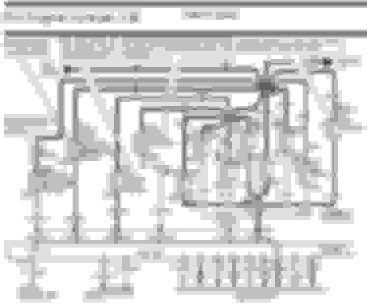
Subford did post the image below on another thread for the pinout connections. Thanks Subford. There are some numbers associated on the wiring but not known (by me) if any refer to what a proper ohm reading would be. If not, does anyone have any suggestions where I should be looking for this info?
I don't think anybody has ever done a full set of resistance measurements as Cardone describes. The variables are staggering and largely meaningless and that is why nobody has compiled a list. This simply is a case of Cardone covering their own nether regions when the customer returns the part. Nothing like being able to say I told you so, even when the process is vague.
Common sense would be your best guide. Hopefully, you have already determined that you truly have a faulty ECM and are not simply throwing parts at a problem. Resistance checks would uncover shorts and opens. Ideally, a piece of wire has a very low resistance, almost 0 ohms. End to end, any given wire should be near 0 ohms. An open circuit would read infinite ohms. There are not a lot of circumstances where resistance is intentionally introduces into a wiring circuit, but a high resistance may indicate corroded wiring or connectors. Insulation prevents wires from touching each other. If insulation breaks down and wires do touch each other, you have a short. Typically, a short between wires would measure as 0 ohms, but sometimes factors like corrosion and contamination will cause a high resistance reading which can be described as a partial short. Either way, unintended shorts are undesirable
If there are any problems in your vehicle wiring that have destroyed the ECM, these should have been discovered during your initial troubleshooting process before you changed the ECM. You need a good wiring diagram and some technical skills to accomplish this. Assumptions are expensive. Keep at it, ask questions and it will all come together.
@ NotEnoughTricks2014, thanks. I was wondering about Cardone's suggestion without referencing where to find such. I had three injector wired destroyed and wildly frayed by pack rats. Those are repaired with a close inspection not turning up any other chewed wires. So hopefully that was the only problem. The old PCM had a blown electrolytic capacitor and one leg of a tantalum capacitor was pretty dark at the board indicating heat. So that pretty well confirmed to me the PCM was bad. I did replace the blown capacitor but still missing on 2367. Lots of transistors and other stuff to blow with no external signs so I'm as convinced as possible that the PCM is bad. New PCM is due in this Monday.
@subford, I'm guessing KOEO is with the PCM plugged in as it obviously is with engine running. Cardone mentioned that one of the most frequent causes of blown PCM's was failed relays which I see several of in the first picture you sent.
I guess I could check those. Seems a relay should have some resistance through the coil but if infinite would indicate a problem. I'm no electronics whiz for certain. I've searched for a complete pinout description of my PCM but came up short there also.
I guess I'll have to just mostly cross my fingers after the new PCM is plugged in.
I guess that you have the E4OD in the post above but do not know if you have an California truck or not.
Would need to know this information before posting a PCM pin-out for you.
@subford, I'm guessing KOEO is with the PCM plugged in as it obviously is with engine running.
That is correct.
Originally Posted by trailscout
Cardone mentioned that one of the most frequent causes of blown PCM's was failed relays which I see several of in the first picture you sent.
Not sure how one of the relays on your truck could damage a PCM.
All of your relay will output either battery voltage or not.
The only relay controlled by the PCM is the fuel pump relay. Maybe a shorted coil in the fuel pump relay may over heat the grounding transistor in the PCM.
But that's about it.
Sticker under the hood says, "Conforms to US EPA standards", without any mention of CA EPA.
Double checked to see if I was quoting Cardone correctly. Here it is:
Quote:Before I put in a new ECM, how do I know that it will fix my problem?
Before installing an ECM, you must test ALL related circuits on the vehicle to determine which one(s) caused the failure. Use the HOT BOX or a DVOM and measure the resistance at the harness connector. If any values are less than the specified ohms, you must find and fix the cause.
SPECIAL NOTE: THE MOST COMMON CAUSE OF ECM FAILURE IS DUE TO ONE OR MORE OF THE ECM CONTROLLED SOLENOIDS / RELAYS SHORTED
But that said, yeah, they did not offer a source for the resistances. I'm still a little puzzled how having the +/- shorted together at the injector would blow the PCM since with the (-) not connected except for milliseconds during firing, why a continual short would blow the PCM. The current wouldn't be going through the coil, so the injector wouldn't open but the PCM wouldn't know that I wouldn't think.
I read somewhere that the positive that is always on for the + side was ignition voltage. But maybe if it goes through a device within the PCM if it was shorted to ground it could heat up something. When the rats chewed up the injector wires is when 2367 went to missing. Everything points toward those injectors blowing the PCM but as some say, there is many a slip between the cup and the lip.
I'll know more after the mail runs Monday....cringe.
I do have the E4OD.
Thanks for the help. This entire affair has been quite a rabbit hole but learning stuff is fun. When I get to drive the pickup it'll be even more fun.
These computers are great, but if one can't be found or the problem causing the failure can't be found, the entire truck becomes just another parts truck. Makes me wonder about going back to points and carbs.
Edit: After reading what Cardone said once again, an injector it seems is a PCM controlled solenoid so that would seem to fit.
Oh boy! I know what I'll be doing between now and Monday afternoon. This is incredible info. All downloaded and saved in my Pickup folder. Thanks a million @subford.
The PCM for the 95 has 1-10 and 10-20 printed on one side. The PCM can't be oriented to match the print out so I'm assuming the printout is for the connector. Unless I'm missing something.
10:44 AM (16 minutes ago) to me Harold, All-Data has no resistance test for these pins. I would suggest to make sure you have no shorts to ground or shorts to power. Thanks
Thank You For Your Busniess
Stan
Cardone Tech Team
888 280 8324
Stanley Choynacky <SChoynacky@cardone.com>
5:04 AM (5 hours ago) to me, Website Thank you for e-mailing us. We would need an application, please feel free to call our tech line at 888 280 8324 and a tech can assist you.
Thank You For Your Busniess
Stan
Cardone Tech Team
888 280 8324
From: Harold Sent: Friday, September 21, 2018 11:09 PM To:tech@cardone.com Subject: External: Tech Question from Cardone.com
Hello,
I have read your recommendation that the pin connectors for the PCM should be checked for proper resistances prior to installation of a replacement PCM.
I am having difficulty finding a source for a chart of the pinout resistances for the harness connections to a Cardone 78-6177.
Rezvani's Latest Post-Apocalyptic Monster Is a Ford F-150 Raptor Underneath
Slideshow: Called the Fortress, the 850-horsepower pickup combines Raptor underpinnings with military-inspired features, survival equipment, and a starting price of $285,000.