


DIR Flasher

Thread Starter
|
Freshman User
Joined: Apr 2009
Posts: 30
Likes: 0
DIR Flasher
I have a 1991 f-250 with a 460. On my wiring digram the oxygen sensor has a wire that says it goes to the DIR flasher. Anybody know what that is? where it goes? Im getting ready to transplant the motor into my 1975 f-250 and am trying to make sure i know where all the wiring goes to before i start. Thanks in advance.
After some searching i know what the dir flasher is. Could someone please explain to me why the oxygen sensor is tied into it?
After some searching i know what the dir flasher is. Could someone please explain to me why the oxygen sensor is tied into it?
Der Postmeister
Joined: Sep 2006
Posts: 6,859
Likes: 560
From: Long Beach, Calimexiforia

I have a 1991 f-250 with a 460. On my wiring digram the oxygen sensor has a wire that says it goes to the DIR flasher. Anybody know what that is? where it goes? Im getting ready to transplant the motor into my 1975 f-250 and am trying to make sure i know where all the wiring goes to before i start. Thanks in advance.
After some searching i know what the dir flasher is. Could someone please explain to me why the oxygen sensor is tied into it?
After some searching i know what the dir flasher is. Could someone please explain to me why the oxygen sensor is tied into it?
Thread Starter
|
Freshman User
Joined: Apr 2009
Posts: 30
Likes: 0
yep thats what the wiring diagram says. all my research shows this to be the directional or turn signal flasher. Why would an engineer hook an o2 sensor to the turn signal flasher? Somebody straighten me out!!!!
Der Postmeister
Joined: Sep 2006
Posts: 6,859
Likes: 560
From: Long Beach, Calimexiforia
That would make it a heated o2 sensor. Still going w/ a shared Ground connection. Notice the multiple grounds off the Battery NEG in the diagram I posted.
Thread Starter
|
Freshman User
Joined: Apr 2009
Posts: 30
Likes: 0
i cant figure out how to get from paper to computer file.
purple/orange- Dir flasher
grey/lt blue-pin 29 computer HEGO
black- ground
orange-pin 49 computer HEGO ground as well as self test output, idle air bypass valve, map, maual lever position sensor, transmission, coolant temp sensor, air charge temp sensor, egr
i got the shared grounds, the o2 ground, the o2 signal input, still confused on dir flasher
Trending Topics

Posting Guru
Joined: Jan 2002
Posts: 1,346
Likes: 8
From: Baltimore
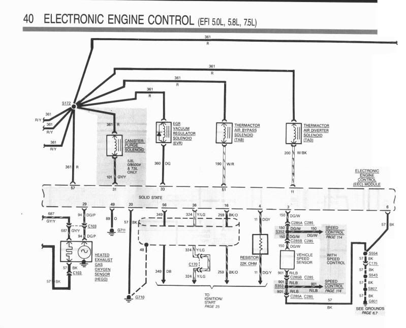
Here's the schematic of the oxygen sensor for a 88. It appears the wiring is
similar to your 91. The 88 has no self test wire.
Bottom left corner shows the heated oxygen sensor.
On the 88 it uses a 3 wire sensor.
The output of the oxygen sensor goes to pin 29 of the computer.
In the schematic it's a Dark Green/Purple wire.
The ground for the oxygen sensor is the body of the sensor which screws
into the exhaust pipe bung. The ground for the heater circuit is a Black wire.
In your case the sensor has 2 ground wires. You can tie them together and
ground them.
The 12 volts for the heater element comes from the ignition switch.
When the ignition switch is in Run/On 12 volts passses thru the ignition switch and provides
12 volts to two circuits.
12 volts goes to Fuse #5 which is the Turn signal flasher.
12 volts also goes to a 20 gauge fusible link and then to the heating
element of the oxygen sensor via a Gray/Yellow wire.
FTE Stories
Ford Trucks for Ford Truck Enthusiasts

Top 10 Fords at 2026 Carlisle Ford Nationals
Joe Kucinski
3 Best / 3 Worst Parts of Modern Ford Ownership
Brett Foote
10 Amazing Upgrades That Solve Common Ford Truck Owner Headaches
Pouria Savadkouei
Every 2026 Ford Engine Explained
Brett Foote
10 Ugly Ford Trucks That We Still Kinda Love
Joe Kucinski
10 Things Every Truck Owner NEEDS (2026 Edition)
Michael S. Palmer
Rezvani's Latest Post-Apocalyptic Monster Is a Ford F-150 Raptor Underneath
Verdad Gallardo
Top 10 Most Expensive Ford Trucks Ever Sold on Bring a Trailer
Joe Kucinski
2027 Ford Super Duty Buyer's Guide (Every Model, Engine, & Package)
Brett Foote
Thread
Thread Starter
Forum
Replies
Last Post