


Wiring help (Julie, I'm looking in your direction)
Thread Starter
|
Elder User
Joined: Nov 2003
Posts: 576
Likes: 9
From: Rockford, IL
Wiring help (Julie, I'm looking in your direction)
I'm currently wiring my '57 and have a few questions for you guys and gals. First a little history. When I bought the truck, there had been a fire under the dash at some point or another and it was a mess. I had just bought a '68 F100 that had a blown motor and a broken rear-end, so I pulled the entire harness, including switches, from the '68 and put it in the '57. It's worked fine, but it's still 40+ years old, which brings me to today. I have a NEW, simple, 8 circuit harness with a max rating of 100 amps total. When I look at the OLD fuse block from the '68, there's a 20A fuse for the heater, a 14A fuse for back up lights (which I don't have anyway), W/S washer, and turn signals, a 2A for instrument cluster, a 15A for dome light and cigar lighter, and a 20A for the emergency flashers. There is no headlight fuse in the fuse block, and I don’t see where one would go in the headlight switch. Did Ford use some kind of circuit breaker in the switch?
Should I run a fused line to the switch for safety's sake? How many amps should the circuit be? I am planning on upgrading to relays in the headlight circuit if that makes any difference.
In regards to the emergency flasher circuit, does it really need to be 20A?
What gauge wire should be used for a 20A circuit?
Here's my list for the eight circuits and the amperage I'm thinking they'll need. Please correct me if I'm wrong, I'd hate to burn down my truck.
Dome light/Dashboard lights - 5A - Hot all the time
Turn Signals - 10A?? - Keyed
Headlights - 20A?? - Hot all the time
Tail lights - 10A - Hot all the time
Cigar Lighter - 15A?? - Keyed
Emergency Flashers - 20A - Hot all the time
Heater - 20A - Keyed
Total Amperage - 100A
I still need to find a spot for wipers, I'm in a pickle.
The combined amperage of all the circuits in the original box was 71 amps. I am not adding any circuits that weren't there already. If the Dome light and Cigar lighter were originally on the same 15A circuit, can I combine them in the new harness, as long as I'm using the same gauge wire? If the turn signals, wipers, and backup lights were all on the same 14A circuit, and I'm not using back up lights, is 10A enough for just the turn signals.
I'm re-using the starting/charging circuit from the '68 because it's still in good shape and the new harness didn't come with one. On the old harness, the main power line from the battery goes to a connection that then runs to the ignition switch, the headlight switch, and the old fuse block; all four wires are pretty heavy gauge. If I'm using headlight relays, does the power wire to the headlight switch need to be as thick?
If I splice a 20A blade fuse holder into the power wire to the headlight switch, I can then use the open spot in the fuse box for wipers. How many amps does a typical wiper motor draw at max load?
Julie, do you still have the charts for wiring? If I PM you my email address could you send them to me?
Finally, there's a small gauge resitor wire (single strand aluminum) that runs from the ignition switch to the connection for the alternator. At the connection there is also a small gauge copper wire that runs back, parallel to the resitor wire, to the charge light. Any idea what the resistor wire does, or why it's a resistor wire and not a standard wire? I'm running all aftermatket gauges, so the charge light is no longer being used. Can the resistor wire be removed?
There's probably more questions that I don't even realize I have, but that's it for now. Thanks, John
I'm gonna post this over on the HAMB as well, the more eyes that see it, the better.

Post Fiend
Joined: May 2008
Posts: 7,641
Likes: 21
From: Poway, Ca.
Hi! I'm here, it just took me a long time to read all that and decipher all the math.
It's a little late and there's a lot of info in your post we can chat about later. But, if you are using an OEM 57 Headlight switch , then yes it has circuit breakers internal to it. It is the same switch and wiring flow used 55-57 except the CBs in the 56/57 switch are 12 volt.
With the accessories you listed you will be very hard pressed to use 50 amps let alone the 70 your alternator is probably rated at or the 100 on your harness. I don't use 70 amps on my truck and my four trumpet horns draw 17 amps per pair!
Your hot items would normally be wired off the headlight switch and the CBs would take care of them. There are a few Hot items that are not circuit protected in this set up - cigar lighter, and horns come to mind.
For your switched items they were usually powered of the "ACC" post on your ignition switch and the low draw items (like gauges) were not protected. The higher draw items like signal lights, heater, wipers and radio were protected by inline fuses.
On the drawings, I am currently changing them to color correct for wiring (except those fo rmy truck). But it really is best to have me send you the original Power Point drawings for a couple of reasons: First, they are much clearer; second, you can enlarge them; and third you can modify them to show your own colors, flow or additions if you want to change them.
The "BUS" (fuse holder) diagrams I have there show the fuse sizes I use on my 12 volt items.
You can send me an e-mail at babbiebuddie@***.net and I will send them to you. Please be certain I have you re-mail address that I can copy and paste because I send those as a "Forward" fro the last person, rather than a reply (so you can see the other questions they've asked as well.)
Look forward to hearing from you.
Thread Starter
|
Elder User
Joined: Nov 2003
Posts: 576
Likes: 9
From: Rockford, IL
For your switched items they were usually powered of the "ACC" post on your ignition switch and the low draw items (like gauges) were not protected. The higher draw items like signal lights, heater, wipers and radio were protected by inline fuses.
On the drawings, I am currently changing them to color correct for wiring (except those fo rmy truck). But it really is best to have me send you the original Power Point drawings for a couple of reasons: First, they are much clearer; second, you can enlarge them; and third you can modify them to show your own colors, flow or additions if you want to change them.
The "BUS" (fuse holder) diagrams I have there show the fuse sizes I use on my 12 volt items.
You can send me an e-mail at babbiebuddie@***.net and I will send them to you. Please be certain I have you re-mail address that I can copy and paste because I send those as a "Forward" fro the last person, rather than a reply (so you can see the other questions they've asked as well.)
Look forward to hearing from you.
Post Fiend
Joined: May 2008
Posts: 7,641
Likes: 21
From: Poway, Ca.
Hi John,
The drawings are on the way. I'm not sure about the 65 headlight switch, but I think by that time they started using fuse panels so the Circuity breakers wouldn't be in there.
Personally, if I had the choice, I wouldn't combine anything on one fuse. Fuses are cheap and the holders are relatively cheap. If you pop a fuse with only one item on it then you know which circuit to test or trouble shoot (or which one to put a bigger fuse in). If you want more than the 8 places you have now, just add another fuse holder, and use the one you have for the hot items and the new one for switched items. You can power the switched items fuse box right off the ignition switch and those items are usually low to moderate draw. Or you can always use a couple inline fuse holders as well. I prefere to th efuse holders as you know where everything is and it's usually more accessable. I think you'll get a better idea when you get the drawings.
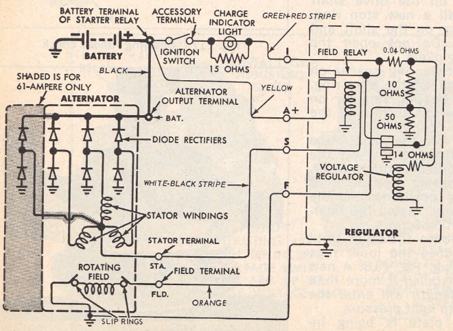
I'm about 95% certain that the aluminum resistor/copper wire is an exciter type set up for your alternator and battery light. You'll need to keep those.
Here's a drawing of a 66 (should be reall close) charging set up with the light (top center):
The drawings are on the way. I'm not sure about the 65 headlight switch, but I think by that time they started using fuse panels so the Circuity breakers wouldn't be in there.
Personally, if I had the choice, I wouldn't combine anything on one fuse. Fuses are cheap and the holders are relatively cheap. If you pop a fuse with only one item on it then you know which circuit to test or trouble shoot (or which one to put a bigger fuse in). If you want more than the 8 places you have now, just add another fuse holder, and use the one you have for the hot items and the new one for switched items. You can power the switched items fuse box right off the ignition switch and those items are usually low to moderate draw. Or you can always use a couple inline fuse holders as well. I prefere to th efuse holders as you know where everything is and it's usually more accessable. I think you'll get a better idea when you get the drawings.
I'm about 95% certain that the aluminum resistor/copper wire is an exciter type set up for your alternator and battery light. You'll need to keep those.
Here's a drawing of a 66 (should be reall close) charging set up with the light (top center):
Trending Topics
Thread Starter
|
Elder User
Joined: Nov 2003
Posts: 576
Likes: 9
From: Rockford, IL
Thanks Julie that's what I was thinking. I got the files, thanks again. As for the headlight switch, there isn't a fuse in the fuse box for headlights, does that mean it's a circuit breaker? Would it hurt to put an inline fuse in there anyway?
FTE Stories
Ford Trucks for Ford Truck Enthusiasts

10 Best Ford Truck Engines We Miss the Most!
Joe Kucinski
2026 Shelby F-150 Off-Road: Better Than a Raptor R?
Brett Foote
2027 Super Duty Carhartt Package First Look: 12 Things You NEED to Know!
Michael S. Palmer
10 Most Surprising 2026 Ford Truck Features!
Joe Kucinski
Top 10 Ford Trucks Coming to Mecum Indy 2026
Brett Foote
5 Best / 5 Worst Ford Truck Wheels of All Time
Joe Kucinski
Ford Super Duty: 5 Things Owners LOVE, 5 Things They LOATHE!
Joe Kucinski
Every 2026 Ford Truck Engine RANKED from WORST to FIRST!
Michael S. Palmer
The Best F-150 Deal of Every Trim Level (XL through Raptor)
Joe KucinskiI'll have the Roast Duck


Joined: Jul 2002
Posts: 9,622
Likes: 108
From: Northshore, MN

Headlights went to circuit breakers, so that when something shorts them out, they go off, and back on, and back off, and back on, etc... So that in the dark, when the lights are on, they don't just go off and stay off where you can't see where you're driving anymore. A fuse that blows, would shut them off completely without coming back on. It's a safety measure.

Thread
Thread Starter
Forum
Replies
Last Post
jvmcc
1948 - 1956 F1, F100 & Larger F-Series Trucks
12
Jul 22, 2016 02:04 AM
Tilleyman
1948 - 1956 F1, F100 & Larger F-Series Trucks
8
Feb 24, 2016 01:05 PM