


Minimum Electrical Connections to Test Run the Engine

Thread Starter
|
Post Fiend
Joined: May 2008
Posts: 7,641
Likes: 21
From: Poway, Ca.
Minimum Electrical Connections to Test Run the Engine
I've been asked a few times this week how to wire the engine up just enough to get it to turn over and run for test purposes.
Finally this third time of typing it out, I thought I'd put it on a thread and save it to the tech library.
So here it is - this is for a Ford engine, 12 volt, negative ground, set up of course. All you SBC guys will have get instructions off another thread.
OK, so lets keep this simple. This is just to run the engine - not to drive it.
There are two areas you need to hook up to get the engine to start and run: Ignition, and Start. You really don't need the Generator/Alternator, but you will have to charge your Battery somehow later.
Parts you will need to get: 12 volt (four post) Starter Solenoid; two post non grounding Starter Button (unless your ignition switch has a "start" position);
12 volt Coil ( I strongly recommend the Petronix "Flame Thrower"); Ballast Resistor; 12 volt Points, and Condenser.
OK Ignition:
All you need to have is power coming from your Starter Solenoid - the one with the POSITIVE Battery Cable hooked to it- hooked up to the "B" or "BATT" post on your Ignition Switch.
Then run a wire off the "I" or "IGN" post of the Ignition Switch to one tab of a Ballast Resistor out the other end of the Ballast Resistor to the POSITIVE post of a 12 volt Coil.
Hook your Distributor wire (from the Points - I think it's white) to the NEGATIVE post on the Coil!
Run one more wire from the POSITIVE post of the Coil to the small "I" post on the Starter Solenoid.
Ignition is done.
Now, run a Battery Cable off the POSITIVE post of the Battery to the large "B" lug (or the one with the wire going to the Ignition Switch), of the new 12 volt (four post) Starter Solenoid.
Run a battery type cable with two eye ring terminals from the other large lug of the Starter Solenoid down to the Starter.
Connect the end of you other Battery Cable to one of the Starter mounting bolts. But don't hook it to the Battery until you are ready to start up the Engine.
Run a 14 AWG wire from the "A" or "ACC" post of the Ignition Switch to a TWO POST Starter Sutton then out the other post of the Starter Button to the "S" small post of the Starter Solenoid.
Start circuit is now complete and the truck will start and run (provided the battery is charged).
If you want to hook up the Generator or Alternator to work, hook up the Regulator to it as you normally would, then run out the "power out" wire ( the same with a one wire just no regulator) to the same post on the Starter Solenoid as the POSITIVE Battery Cable.
With this set up, to start the truck:
Connect the NEGATIVE Battery Cable (the one bolted to the Starter mounting bolt) to the NEGATIVE post of the Battery.
Push the Accelerator Pedal to the floor and pull the Choke Cable out 1/2 way - release the Accelerator pedal.
Turn the Ignition Switch ON and push the Starter Button (or click over to the start position). Should start right up and run.
To turn it off, turn the Ignition Switch OFF.
A few caveats. Folks are going to tell you you can use a toggle to turn on power, or push the button on the start solenoid (not on a 12 volt), etc etc.
You are going to have to buy and install the ignition switch, starter button, etc etc eventually any way - just do it now and test the wiring an hook up s as well now. No sense in jerry rigging then rewiring and retesting the real set up later - that's silly.
Just remember you don't have any gauges or instruments - use caution with oil pressure or temperature accordingly!
Pic:
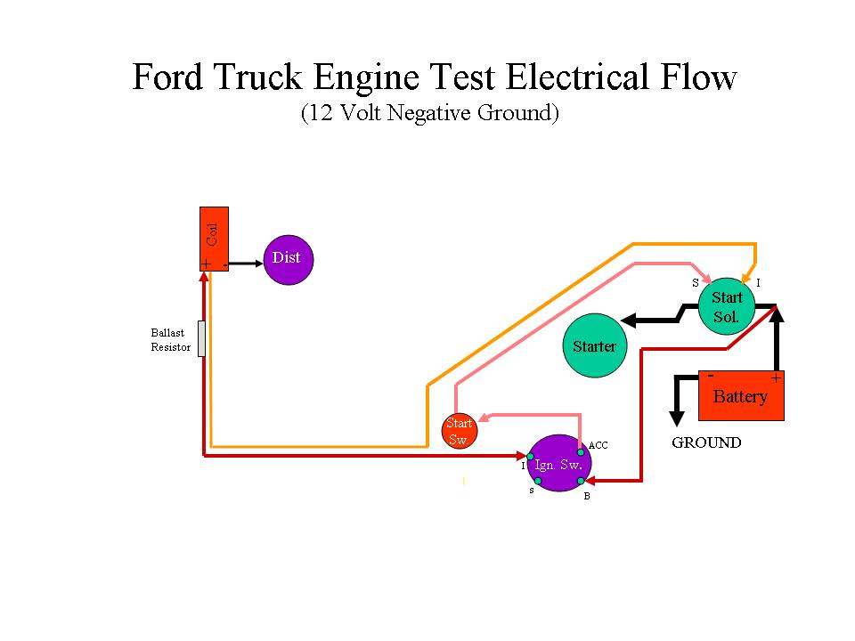
Edited to show 12 Volt Negative Ground Diagram
Finally this third time of typing it out, I thought I'd put it on a thread and save it to the tech library.
So here it is - this is for a Ford engine, 12 volt, negative ground, set up of course. All you SBC guys will have get instructions off another thread.
OK, so lets keep this simple. This is just to run the engine - not to drive it.
There are two areas you need to hook up to get the engine to start and run: Ignition, and Start. You really don't need the Generator/Alternator, but you will have to charge your Battery somehow later.
Parts you will need to get: 12 volt (four post) Starter Solenoid; two post non grounding Starter Button (unless your ignition switch has a "start" position);
12 volt Coil ( I strongly recommend the Petronix "Flame Thrower"); Ballast Resistor; 12 volt Points, and Condenser.
OK Ignition:
All you need to have is power coming from your Starter Solenoid - the one with the POSITIVE Battery Cable hooked to it- hooked up to the "B" or "BATT" post on your Ignition Switch.
Then run a wire off the "I" or "IGN" post of the Ignition Switch to one tab of a Ballast Resistor out the other end of the Ballast Resistor to the POSITIVE post of a 12 volt Coil.
Hook your Distributor wire (from the Points - I think it's white) to the NEGATIVE post on the Coil!
Run one more wire from the POSITIVE post of the Coil to the small "I" post on the Starter Solenoid.
Ignition is done.
Now, run a Battery Cable off the POSITIVE post of the Battery to the large "B" lug (or the one with the wire going to the Ignition Switch), of the new 12 volt (four post) Starter Solenoid.
Run a battery type cable with two eye ring terminals from the other large lug of the Starter Solenoid down to the Starter.
Connect the end of you other Battery Cable to one of the Starter mounting bolts. But don't hook it to the Battery until you are ready to start up the Engine.
Run a 14 AWG wire from the "A" or "ACC" post of the Ignition Switch to a TWO POST Starter Sutton then out the other post of the Starter Button to the "S" small post of the Starter Solenoid.
Start circuit is now complete and the truck will start and run (provided the battery is charged).
If you want to hook up the Generator or Alternator to work, hook up the Regulator to it as you normally would, then run out the "power out" wire ( the same with a one wire just no regulator) to the same post on the Starter Solenoid as the POSITIVE Battery Cable.
With this set up, to start the truck:
Connect the NEGATIVE Battery Cable (the one bolted to the Starter mounting bolt) to the NEGATIVE post of the Battery.
Push the Accelerator Pedal to the floor and pull the Choke Cable out 1/2 way - release the Accelerator pedal.
Turn the Ignition Switch ON and push the Starter Button (or click over to the start position). Should start right up and run.
To turn it off, turn the Ignition Switch OFF.
A few caveats. Folks are going to tell you you can use a toggle to turn on power, or push the button on the start solenoid (not on a 12 volt), etc etc.
You are going to have to buy and install the ignition switch, starter button, etc etc eventually any way - just do it now and test the wiring an hook up s as well now. No sense in jerry rigging then rewiring and retesting the real set up later - that's silly.
Just remember you don't have any gauges or instruments - use caution with oil pressure or temperature accordingly!
Pic:
Edited to show 12 Volt Negative Ground Diagram
Laughing Gas
Joined: Jan 2008
Posts: 758
Likes: 0
From: Alabama
Julie your a blessing when it comes to this wiring of our old trucks! Thank you for taking the time to do these write ups. I'm getting close to wiring my engine up and cranking it for the first time. One thing I'm fuzzy on, 351W 12 volt system, I have one of the distributors without points and condensor. Do I still need the ballast resistor? I'm not sure what the resistor acutally does in the circuit.
Thread Starter
|
Post Fiend
Joined: May 2008
Posts: 7,641
Likes: 21
From: Poway, Ca.
Since the 6V Positive Ground system was developed before writing, will just a picture do for now? LOL!
Julie your a blessing when it comes to this wiring of our old trucks! Thank you for taking the time to do these write ups. I'm getting close to wiring my engine up and cranking it for the first time. One thing I'm fuzzy on, 351W 12 volt system, I have one of the distributors without points and condensor. Do I still need the ballast resistor? I'm not sure what the resistor acutally does in the circuit.
No not yet! I recently inherited a SUM of money so I am retiring young (45) to work on my little California Ranch (its paid for) - 14 more days. Maybe I'll get a paper route or something!
Senior User
Joined: Nov 2009
Posts: 223
Likes: 0
From: wichita falls, texas
julie, you are perhaps the only person i know of that has their cali property paid for. CONGRATS!!!!!!!! the way property prices have been out there for years(or decades) that is amazing! esp if it is in the poway area.
i have a pertronix conversion for one of my old mustangs that i havent installed yet. any idea if i'd need the ballast for it? their paperwork doesnt say anything one way or the other.
i have a pertronix conversion for one of my old mustangs that i havent installed yet. any idea if i'd need the ballast for it? their paperwork doesnt say anything one way or the other.
Thread Starter
|
Post Fiend
Joined: May 2008
Posts: 7,641
Likes: 21
From: Poway, Ca.
Thanks. The family had a few other properties and I had a house in the midwest I sold, then paid cash for the ranch - it had been previously owned by a very elderly gentleman who passed away, and was in a serious state of dis repair-it's been a lot of time and money but is coming along nicely. I have relatives living here who have helped quite a bit. Old projects in disrepair that take lots of time and money seem to be my forte lately!
Ballast resistors - the only time you should need a ballast resistor is if you are using traditional points ignition in a 12 volt electrical system. So unless the unit specifically calls for one, then I would say no to the ballast resistor.
Ballast resistors - the only time you should need a ballast resistor is if you are using traditional points ignition in a 12 volt electrical system. So unless the unit specifically calls for one, then I would say no to the ballast resistor.
Trending Topics

Freshman User
Joined: Jun 2010
Posts: 48
Likes: 0
Julie,
Can you help me out yet again? In my saga of getting my 65 f100 started: Now that I have new gas tank and filter and fuel pump I have gas spewing everywhere when cranking - carb way over flooded so I and I suspect the jets are still clogged from all the old gas and crud that went through before I removed old tank.
TRYING to get rebuild kit or replacement - NAPA has the basic rebuild kit but now they aren't sure it is actually for MY Carb.
Here is the numbers I can find on that carb:
6-1978
YF64208 (unless the "6" is a "G")
Built by Carter for Ford
NAPA said if I could research this then they might be able to help.
Any ideas?
Also - I am still learning just how to post inquiries on this site; found your thread here and replied to that one.
Thanks,
Michael
FTE Stories
Ford Trucks for Ford Truck Enthusiasts

Top 10 Most Expensive Ford Trucks Ever Sold on Bring a Trailer
Joe Kucinski
2027 Ford Super Duty Buyer's Guide (Every Model, Engine, & Package)
Brett Foote
Top 10 Ford Truck Tragedies
Joe Kucinski
AEV FXL Super Duty - the Super Duty Raptor Ford Doesn't Make
Brett Foote
Lobo Vs Lobo: Proof the F-150 Lobo Should Be Even Lower!
Michael S. Palmer
Ford's 2001 Explorer Sportsman Concept Looks For a New Home
Verdad Gallardo
10 Best Ford Truck Engines We Miss the Most!
Joe Kucinski
2026 Shelby F-150 Off-Road: Better Than a Raptor R?
Brett Foote
2027 Super Duty Carhartt Package First Look: 12 Things You NEED to Know!
Michael S. Palmer
Thread Starter
|
Post Fiend
Joined: May 2008
Posts: 7,641
Likes: 21
From: Poway, Ca.
Hi Michael,
I think you are right, it sounds like the carb is all crudded up - needle valve that shuts off gas included.
The guy you want to ask about the carb numbers is "Number Dummy." If you have a number, Bill can tell you what it's for and usually where to get one or the parts to fix it.
If he doesn't come on here, I'd send him a PM. To do that, open the link I'll post below, find the post by "Number Dummy" (#14) and click on his name - you will have the option to send him a Private Message.
If it doesn't work, let me know and I'll ask him to come on here.
https://www.ford-trucks.com/forums/9...off-valve.html

New User
Joined: May 2010
Posts: 3
Likes: 0
From: Sterling, CO
Hi folks, new member here (my first post).
Julie, I modified your drawing to show the way I test start an engine. Hope you don't mind.
You will need a jumper wire with alligator clips at each end long enough to reach from the battery or bat side of the solenoid to the coil.
You will also need a remote starter button. You can buy them at auto parts stores or make one. Mine is a double pole push button I found in my junk box that was the right size to fit in a bicycle handle bar grip. Run a piece of household lamp cord through the other end of the grip and put two alligator clips on it.
To start the engine connect the jumper cable to the coil and press the remote button. To stop the engine remove the jumper from the coil.
Notice I don't connect the ballast resister for this test. You won't be running the engine long enough to harm the points.
If the leads on the remote button are long enough you can operate the starter from either side of the vehicle while working the throttle linkage and/or squirting starter fluid into the carb. Incidentally WD-40 is a great starting fluid.
To start a 6 volt posative ground engine you will need 6 volt coil and reverse the
leads so plus goes to distibutor and jumper goes to minus. Also make sure the negative battery cable goes to the solenoid and positive to ground.
If you leave the jumper disconnected from the coil you can use the remote starter button to bump the engine over to TDC for tune ups, etc.
Bill
Thread Starter
|
Post Fiend
Joined: May 2008
Posts: 7,641
Likes: 21
From: Poway, Ca.
......
A few caveats. Folks are going to tell you you can use a toggle to turn on power, or push the button on the start solenoid (not on a 12 volt), etc etc.
You are going to have to buy and install the ignition switch, starter button, etc etc eventually any way - just do it now and test the wiring an hook up s as well now.
Just one question on that: How do you turn it off?
New User
Joined: May 2010
Posts: 3
Likes: 0
From: Sterling, CO
As mentioned in my original post disconnect the jumper from the coil to stop the engine. I like to be able to do all my work under the hood rather than run around to the cab to shut her down if something (fire, whatever) goes wrong. This method has worked for me for over 40 years. Course, now days, I don't even try to diagnose the new computer cars.
BTW To bad we didn't meet up a while back. I just moved from Rancho Penasquitos to Colorado last year. Course then I had a '54 flat fender Power Wagon and half a dozen antique farm tractors.
Got my eye on a '51 F3 at an estate auction in the next couple of weeks so maybe I can become a real member of FTE.
Bill


New User
Joined: Apr 2010
Posts: 16
Likes: 0
julie-
thanks for your 6 volt diagram. perhaps i'll be able to start my 49 this summer.(if i can get the wife feeling better, and keep her that way)
congrats on your upcoming retirement. hopefully someday i'll be able to do the same.(keep your fingers crossed for me)
dave
thanks for your 6 volt diagram. perhaps i'll be able to start my 49 this summer.(if i can get the wife feeling better, and keep her that way)
congrats on your upcoming retirement. hopefully someday i'll be able to do the same.(keep your fingers crossed for me)
dave