Did the search for ammeter wiring
#1
 06-14-2010, 10:06 PM

Did the search for ammeter wiring
I finally got my instrument cluster installed; have the 1950 repo manual, I've converted to 12 volt because I have 1990 Crown vic donor, so.....
I need insight on wiring in the ammeter (not stock; from 1989 Econoline Van) , so it reflects total current draw on the electrical systems. My thoughts are to source 30 Amp circuit from my fuse panel, which is only hot when ignition key is on; to feed to the original 30 amp breaker attached to the instrument cluster, which in turn will feed series power to the instrument gauges. Do I have to parallel the other loads, in order to get a true draw through the ammeter.
Julie , the clock is ticking. I do have the period wiring diagrams, but obviously with 12 volt this will vary a bit.
Come back.
#2
06-15-2010, 01:59 AM

Post Fiend
Being 6 or 12 volt isn't as crucial as how you are flowing your power distribution, and how you are running your charging circuit (Alternator? Generator?). You can't use the existing breakers on the panel, they are for 6 volt.
You should have your generator/alternator charge going straight into your hot fuse panel (for items that are powered all the time - ie headlights, brake lights, horns, courtesy lights, etc) - then up to "BATT" stud on the ignition switch. From there up through the ammeter then out to the battery cable post of the starter solenoid.
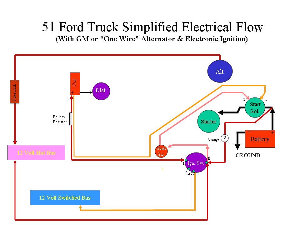
The power going to a second fuse panel for the items that come on with the ignition should come down from the "ACC" post of the ignition switch. The gauge will only show an accurate charge or discharge if it has power flow capability from both sides generator/alternator on one side and battery on the other.
Here's a drawing that wil help you hook up the actual amp gauge if it's not the traditional induction loop:
You should have your generator/alternator charge going straight into your hot fuse panel (for items that are powered all the time - ie headlights, brake lights, horns, courtesy lights, etc) - then up to "BATT" stud on the ignition switch. From there up through the ammeter then out to the battery cable post of the starter solenoid.
The power going to a second fuse panel for the items that come on with the ignition should come down from the "ACC" post of the ignition switch. The gauge will only show an accurate charge or discharge if it has power flow capability from both sides generator/alternator on one side and battery on the other.
Here's a drawing that wil help you hook up the actual amp gauge if it's not the traditional induction loop:
#3
06-15-2010, 09:24 AM
#4
06-15-2010, 09:51 AM

the new voltage meters don't need to do that.. (and why they were built really, to stop having to drag ALL the power to the dash area
sam
#5
06-15-2010, 10:49 AM
Tom, just a quick heads up, you ammeter isn�t, it�s a volt meter calibrated to read in amps. It should be wired in parallel, just wired to 12v hot / switched and ground not in series with everything going thru it.
Julie, I did not read your complete post, no time this AM, so you might have said that, just wanted to catch Tom before the fire!

Julie, I did not read your complete post, no time this AM, so you might have said that, just wanted to catch Tom before the fire!
#6
06-16-2010, 02:51 PM

Thread
Thread Starter
Forum
Replies
Last Post
jvmcc
1948 - 1956 F1, F100 & Larger F-Series Trucks
12
07-22-2016 02:04 AM
FrankGRUN
1968-Present E-Series Van/Cutaway/Chassis
3
06-26-2016 12:53 PM
FrankGRUN
Electrical Systems/Wiring
0
06-25-2016 01:01 PM