

Need some help tracking a diagram down

Thread Starter
|
Junior User
Joined: Oct 2009
Posts: 56
Likes: 0
Need some help tracking a diagram down
I am trying to figure out my vacuum diagram in an effort to fix up my vacuum lines. I dont know what all the different components are (couldn't point to half of them under the hood), and I also dont know how much the PO has messed with things. I have a picture of the vacuum diagram from under the hood:
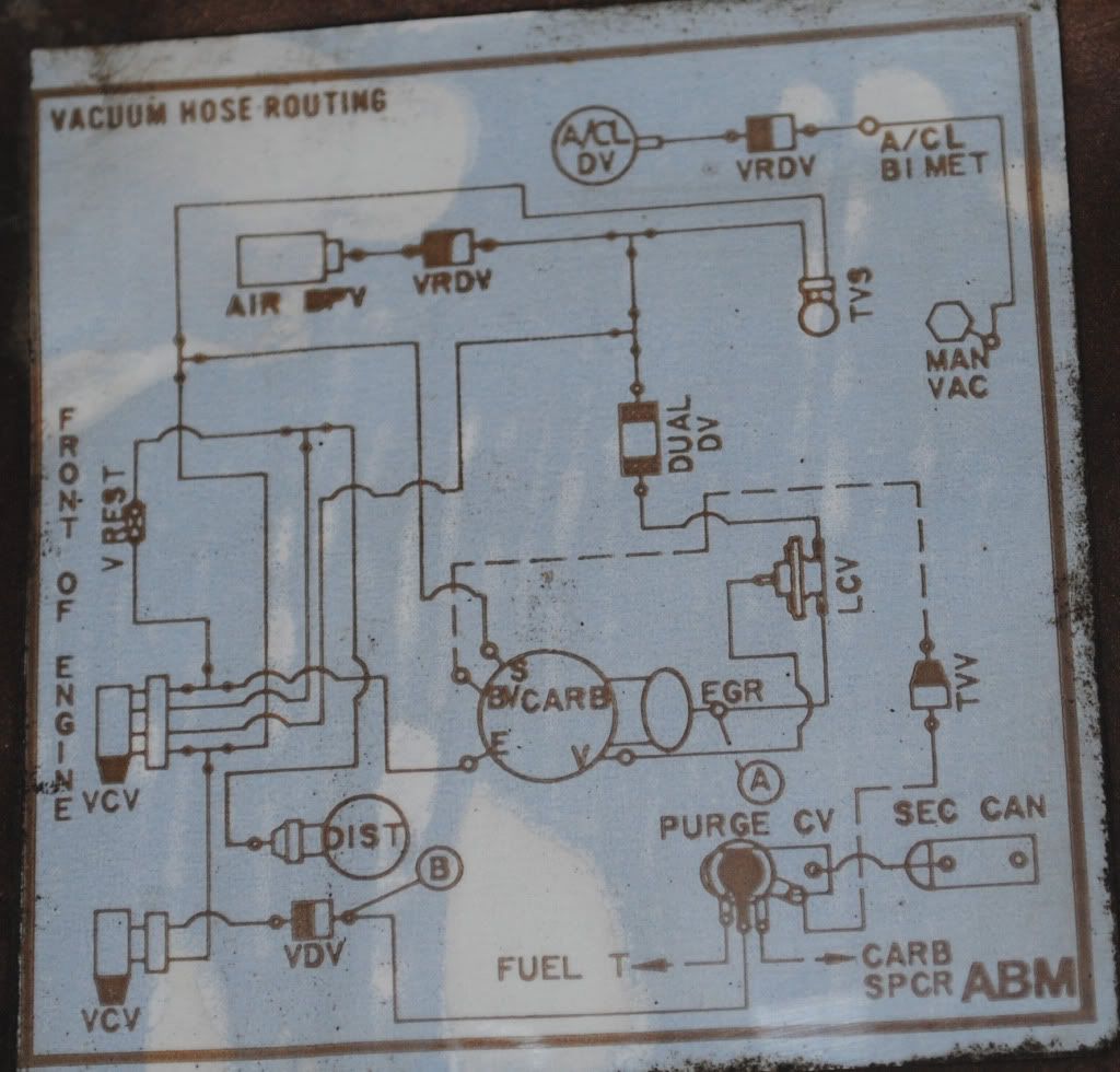
http://i8.photobucket.com/albums/a8/...n/DSC_0256.jpg
I think that
VDV = Vacuum delay valve
VRDV = vacuum retard delay valve
TVS = thermal vacuum switch
Air BPV = Air bypass valve
A/CL BIMET = air cleaner bimetallic sensor
A/CL DV = air cleaner duct and valve vacuum motor (?)
VCV = vacuum control valve
TVV = thermal vent valve
EGR = exhaust gas recirculator
Dual DV = dual delay valve
VREST = vacuum restrictor
Purge CV = Purge Control valve
Sec CAN = secondary canister
not sure about the others on the diagram...
In trying to figure all this out, I found this diagram on one of the threads in this forum:

http://i649.photobucket.com/albums/u...0/7-72-R11.jpg
This looks like it could really help if I could find the right one. What diagram is this exactly? Does anyone know where I can get a diagram like this for my truck? I have a 79 F150, 351M (supposedly).
In case anyone is interested, here is the other emissions label under the hood.

http://i8.photobucket.com/albums/a8/...n/DSC_0257.jpg
http://i8.photobucket.com/albums/a8/...n/DSC_0256.jpg
I think that
VDV = Vacuum delay valve
VRDV = vacuum retard delay valve
TVS = thermal vacuum switch
Air BPV = Air bypass valve
A/CL BIMET = air cleaner bimetallic sensor
A/CL DV = air cleaner duct and valve vacuum motor (?)
VCV = vacuum control valve
TVV = thermal vent valve
EGR = exhaust gas recirculator
Dual DV = dual delay valve
VREST = vacuum restrictor
Purge CV = Purge Control valve
Sec CAN = secondary canister
not sure about the others on the diagram...
In trying to figure all this out, I found this diagram on one of the threads in this forum:
http://i649.photobucket.com/albums/u...0/7-72-R11.jpg
This looks like it could really help if I could find the right one. What diagram is this exactly? Does anyone know where I can get a diagram like this for my truck? I have a 79 F150, 351M (supposedly).
In case anyone is interested, here is the other emissions label under the hood.
http://i8.photobucket.com/albums/a8/...n/DSC_0257.jpg

Postmaster
Joined: Jul 2001
Posts: 4,956
Likes: 10
From: MD
The diagram under your hood is the diagram to follow, not the one you found on here as that is for earlier years.
LCV = Load Control Valve
On the carb:
S = spark port
E = ev/em port
BV = bowl vent
V = venturi port
FUEL T = fuel tank
Carb SPCR = carburetor spacer
LCV = Load Control Valve
On the carb:
S = spark port
E = ev/em port
BV = bowl vent
V = venturi port
FUEL T = fuel tank
Carb SPCR = carburetor spacer
Thread Starter
|
Junior User
Joined: Oct 2009
Posts: 56
Likes: 0
Thanks for the info Jerma. I do have an Edelbrock carb and manifold: If these ports are not present on these parts, can I just cap off the feed lines that would have gone to the S, E, BV, and V ports and carb spacer?
I figured that I would need a diagram specific to my year. I was wondering if anyone knew where I could get the right one. Is it in the shop manual?
I figured that I would need a diagram specific to my year. I was wondering if anyone knew where I could get the right one. Is it in the shop manual?

Thread
Thread Starter
Forum
Replies
Last Post
78_f800crewcab4x4
1973 - 1979 F-100 & Larger F-Series Trucks
44
Jul 29, 2022 05:21 PM
scottaklassen
1968-Present E-Series Van/Cutaway/Chassis
6
Feb 16, 2011 10:24 AM


