


ballest resistor
Logistics Pro

Joined: Feb 2005
Posts: 3,952
Likes: 117
From: Upper Left Coast
Howdy,
The Ballast Resistor is simply a series resistor that goes in the A+ (12V) power wire going to your ignition coil so that during normal running the coil only "sees" about 6v dc. IF you continuously ran 12v to a 6v coil it could eventually overheat.
The Ballast Resistor is bypassed only when the starting motor is powered so as to provide 12v to your coil and maximum spark for starting.
When you release the key (to RUN), the resistor is back in the picture.
Most automotive coils installed with a ballast resistor are 6v coils.
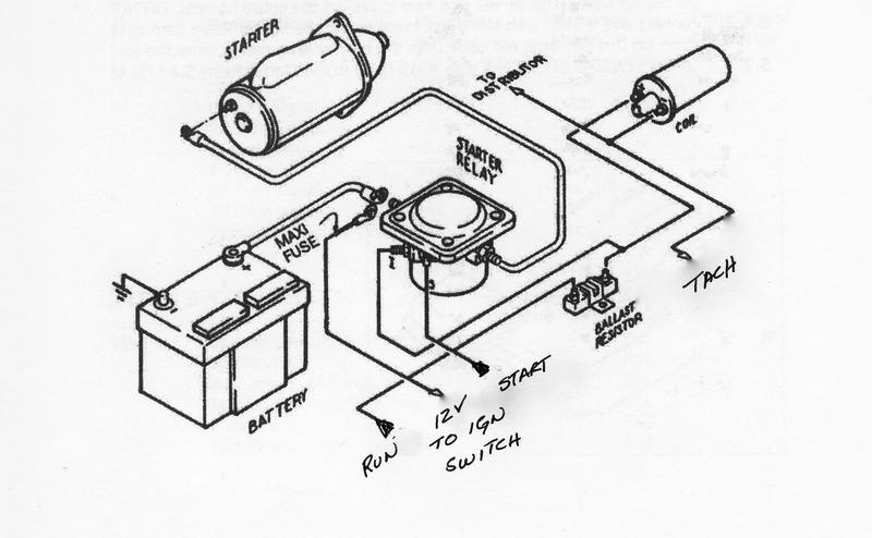
If you look at the simple diagram below, the ballast resistor would go between the battery and + side of the coil.
It would wired so that when the key is turned to START, it would short across the resistor so that it would be effectively bypassed, so the coil would get the full battery voltage during cranking.
When you release the key, the "short" across the resistor would be removed and it would drop the voltage to the coil back to approx 6v for continuous running....
Some people use 12v coils nowadays making the Ballast Resistor unnecessary.

The Ballast Resistor is simply a series resistor that goes in the A+ (12V) power wire going to your ignition coil so that during normal running the coil only "sees" about 6v dc. IF you continuously ran 12v to a 6v coil it could eventually overheat.
The Ballast Resistor is bypassed only when the starting motor is powered so as to provide 12v to your coil and maximum spark for starting.
When you release the key (to RUN), the resistor is back in the picture.
Most automotive coils installed with a ballast resistor are 6v coils.
If you look at the simple diagram below, the ballast resistor would go between the battery and + side of the coil.
It would wired so that when the key is turned to START, it would short across the resistor so that it would be effectively bypassed, so the coil would get the full battery voltage during cranking.
When you release the key, the "short" across the resistor would be removed and it would drop the voltage to the coil back to approx 6v for continuous running....
Some people use 12v coils nowadays making the Ballast Resistor unnecessary.
Thread Starter
|
Freshman User
Joined: Feb 2010
Posts: 36
Likes: 0
OK that helps some. Although since my 60 uses a 12 volt system I'm a little confused about the 12 v dropping down to 6v thing. The diagram was a big help though. Now I just need to run a contenuity test to find the other end of the wire coming off of the coil, since it dissapeares into a wiring hearness and then under the dash as it head's toward the ignition switch, and wiring oblivion.
Logistics Pro
Joined: Feb 2005
Posts: 3,952
Likes: 117
From: Upper Left Coast
That is a problem if you do not have a decent diagram for your wiring system......
Most wiring systems use the power to the starter solenoid (which is activated when you turn the key to "START" to "bypass" the ballast resistor.
They basically run a wire from the hot lead on the starter solenoid to the coil so the coil gets 12v any time the starter solenoid is getting power.
When you release the key, the "regular" (RUN) path of power is from the ignition switch to the ballast resistor then to the coil.
Thread Starter
|
Freshman User
Joined: Feb 2010
Posts: 36
Likes: 0
Heres another noodler. The replacement resistor wire has male "bullet" connectors at both end's. I cant find any such connectors from the distributor or the starter solenoid. So I'm wondering if the wire is connected to the starter switch and run's under the dash somewhere.
Logistics Pro
Joined: Feb 2005
Posts: 3,952
Likes: 117
From: Upper Left Coast
If you want to wire that think up like Ford intended, you'll have to either find an OEM service manual or someone that has a similar truck that can show you were it is, or,
Simply install the resistor in series with the ignition power coming from the key. THEN run a separate wire from the starter solenoid that has power on it during starting directly to the "+" terminal on the coil.
This way, when the key is "ON" the power supplied to the coil with be through the resistor. When you crank the starter, power supplied to the coil will be from the solenoid (and the full 12v).
Here's another good description with a picture.... Ignition Systems* A Short Course
Thread Starter
|
Freshman User
Joined: Feb 2010
Posts: 36
Likes: 0
Great article, thanks. I had another thought [scary]. At the risk of over simplifying the problem, could I install a coil that already has an internal resistor and just ignore the external one?
Trending Topics
Postmaster
Joined: Jul 2003
Posts: 2,688
Likes: 4
From: Southern Oregon
I run a regular black coil which doesnt have internal resistence, and before it is an inexpensive ceramic ballast resistor ($5.00). Easy install.
There is a nice chrome Pertronix coil on the shelf that could be had by someone.
FTE Stories
Ford Trucks for Ford Truck Enthusiasts

Top 10 Fords at 2026 Carlisle Ford Nationals
Joe Kucinski
3 Best / 3 Worst Parts of Modern Ford Ownership
Brett Foote
10 Amazing Upgrades That Solve Common Ford Truck Owner Headaches
Pouria Savadkouei
Every 2026 Ford Engine Explained
Brett Foote
10 Ugly Ford Trucks That We Still Kinda Love
Joe Kucinski
10 Things Every Truck Owner NEEDS (2026 Edition)
Michael S. Palmer
Rezvani's Latest Post-Apocalyptic Monster Is a Ford F-150 Raptor Underneath
Verdad Gallardo
Top 10 Most Expensive Ford Trucks Ever Sold on Bring a Trailer
Joe Kucinski
2027 Ford Super Duty Buyer's Guide (Every Model, Engine, & Package)
Brett FooteSenior User
Joined: Sep 2004
Posts: 323
Likes: 3
From: m571.com/yblock
I also use one of the ceramic resistors with a big yellow Accel "Supercoil." However, after an inconvenient situation, I always carry a spare resistor in the glove box. Along with this, I also use an old Judson "SeeDee" unit, but only as a switch triggered by the points for the coil. This cuts down on the amount of current the points have to handle and makes them last considerably longer. If this SeeDee unit goes bad, it is a simple matter to bypass it and run the motor in a conventional fashion.
Sometimes, it seems counter-intuitive to have a ballast resistor in series with the coil's primary windings. After all, the idea is to have a hot spark, and the more current passing thru the primary windings, the hotter of a spark should be produced.
If you touch one of the external resistors when your engine is idling, you'll note that it can get warm -- sometimes quite warm. The idea here is that when the engine is running slow or idling, there is a lot of current going thru the coil because the points are being held closed for long periods of time. This high current will not only cause the points to arc, but arcing will also occur as the field in the coil collapses, causing an even stronger arc.
What the ballast resistor does is cut that primary current when the engine is running slowly and the points are closed for relatively long periods of time. The resistor heats up and its resistance increases. As the engine speeds up and the primary current drops, the ballast resistor will cool and allow more current to pass thru the primary windings.
The effect of the ballast resistor is to limit the current at slower speeds, so that it remains more constant across the rpm range of the engine.
There are some coils that do have a ballast resistance built into them. If you know that this is the case with one you intend to use, your problem is solved. However, be aware that some cars did not use a separate ballast resistor -- this function was built in to the special coil primary wire, somewhat like resistor spark plug wires.
Logistics Pro
Joined: Feb 2005
Posts: 3,952
Likes: 117
From: Upper Left Coast
There are some coils that do have a ballast resistance built into them.
A ignition coil is simply a transformer with a high "turns ratio" where the "bottom" of both the primary and secondary windings are connected to ground.
A 12v coil is just that. It's a coil with enough resistance in the primary winding to operate directly at 12v. I guess you could say that a 12v coil has the resistor "built-in" but it's not a separate carbon or wire-wound resistor residing inside.....
The primary winding is wound with enough (turns) resistance to provide the correct resistance so the continuous current rating is not exceeded when the points are closed and the primary is powered.
I had an oil filled 12v coil I used on my 57 Ford 292 for many years. I completely eliminated the "ballast" resistor permanently. It never even got warm.
The main downside of using a 12v coil is when your battery is weak.
If you crank the engine with a weak battery, the terminal voltage can get as low as 10v or lower while the starter is operating. Low voltage on a 12v coil can result in a pretty weak spark.
With a 6v coil and an outboard voltage dropping (Ballast) resistor, you would get that same 10v or so directly to the coil because the dropping resistor is switched out of the circuit while cranking.
The result is still a fairly strong spark even though the battery is a little weak.....
It was never a problem for me because I always had a good battery in the car.
Elder User
Joined: Dec 2006
Posts: 559
Likes: 0
From: Redondo Beach, CA
OK Ford Ignition wiring diagram... Notice on the starter SOLENOID the "I". When you turn the switch to start, not only does the solenoid activate the starter MOTOR but it BYPASSES the BALLAST resistor. Very simple. Isn't this what the original question was? "Does anyone know where that wire runs and connects to?" Maj. Spoons, I hope that helps you.
Mike to answer your question, you have lower secondary voltage from the coil due to lower voltage to the primary windings in the coil...
Mike to answer your question, you have lower secondary voltage from the coil due to lower voltage to the primary windings in the coil...
Logistics Pro
Joined: Feb 2005
Posts: 3,952
Likes: 117
From: Upper Left Coast
BTW, That diagram will work on any engine.....
If you have a simple digital or analog volt meter, put it on the + side of the coil and you'll see. It will simply reduce the voltage to the coil.
If that coil requires 12v to produce a hot spark and you only run it with 6 or 8 v on it, it'll just produce a lower voltage spark. It may still be enough "spark" to run the engine though.
Your best bet is to run the right voltage for whatever coil/resistor (or no resistor)combination you're using.