



Installing powerlocks/keyless entry/ alarm.

Thread Starter
|
Freshman User
Joined: Dec 2009
Posts: 39
Likes: 0
Installing powerlocks/keyless entry/ alarm.
Well after install many of stero's,wiring phone system,etc I though I could install powerlocks on my 07 f150 xl.
I have a basic understanding on how this alarm works but I have a few questions. First her is the diagrams I have to look at.
http://tintnelectronics.com/manuals/aga1001.pdf
Like I said I have installed the power locks in the door panels but I do not know how to hook them up the the brain. Do i use relays? or do I just connect a lock wire and a unlock wire to the lock motor? If I do use a relay do Can i daisy chain the unlock output and the lock output?
Once I can get that firgured out I just wire the rest of the brain up to the information I have for the wiring diagram for my truck. 12V to the ignation, Find lights,etc
I`ve gotten this farm and my wife is on my back about "should have just brought it to bestbuy" but hey 8 beers and i`m feeling good I got the door panels off =)
I have a basic understanding on how this alarm works but I have a few questions. First her is the diagrams I have to look at.
http://tintnelectronics.com/manuals/aga1001.pdf
Like I said I have installed the power locks in the door panels but I do not know how to hook them up the the brain. Do i use relays? or do I just connect a lock wire and a unlock wire to the lock motor? If I do use a relay do Can i daisy chain the unlock output and the lock output?
Once I can get that firgured out I just wire the rest of the brain up to the information I have for the wiring diagram for my truck. 12V to the ignation, Find lights,etc
I`ve gotten this farm and my wife is on my back about "should have just brought it to bestbuy" but hey 8 beers and i`m feeling good I got the door panels off =)
Thread Starter
|
Freshman User
Joined: Dec 2009
Posts: 39
Likes: 0
also if I do need to use the relay withc on of these do I use Car Security and Convenience, Power Door Locks, Multiple Wire Systems, Add Auto Lock/Unlock

Post Fiend
Joined: May 2006
Posts: 10,007
Likes: 4
From: Central Florida
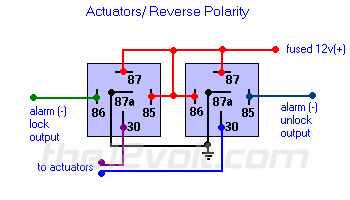
I would use relays, the brain should only handle an amp or so of power, the actuators probably at least that. I don't know how you intend to daisy chain the relays, but I believe the typical install is two relays.
Post Fiend
Joined: May 2006
Posts: 10,007
Likes: 4
From: Central Florida
I think it's actually parallel rather than series, series could work but it would drive up the impedance. Lock wire 1 <--- relay---> Lock wire 2 and Unlock wire 1 <--relay--> unlock wire 2.
If you look at the diagram, instead of only one wire from the 30 poles, you would run two
If you look at the diagram, instead of only one wire from the 30 poles, you would run two
Thread Starter
|
Freshman User
Joined: Dec 2009
Posts: 39
Likes: 0
Ok went to pepboys to buy 2 relays... I had to do some custom work to them but still no lock.. I am confused at what wires on my above diagram I have to connect to the realys. I was looking on ebat and i found this. Should I just spen 7 bucks and buy this.DOOR LOCK RELAY MODULE FOR CAR ALARM - eBay (item 310183455252 end time Dec-20-09 18:11:45 PST)
Post Fiend
Joined: May 2006
Posts: 10,007
Likes: 4
From: Central Florida
You pretty much have that already. If you have the relays wired like I showed, then Relay one gets the white wire from the brain box on terminal 85. Relay 2 gets the wht/blk wire from the brain to the 85 terminal. This way when one wire is pulsed, it engages the relay and sends power to the motors.
Trending Topics
Thread Starter
|
Freshman User
Joined: Dec 2009
Posts: 39
Likes: 0
Ok on the diagram you see ralay 1 terminal 85 with a line to 86 with a t split connect to 87 on the same relay... Then its looks like you connect it to 85 and 87 on relay 2? is this correct or am i using wires from the brain instead of tieng 4 wires togather. Now what do I do with the orages and yellows?
Thanks for the help so far.. I did order the part but if i can get it to work before I get it.. I`ll just return it.
Thanks for the help so far.. I did order the part but if i can get it to work before I get it.. I`ll just return it.
FTE Stories
Ford Trucks for Ford Truck Enthusiasts

Top 6 Best Deals Available on New Fords & Lincolns Right Now
Brett Foote
This Hennessey Takes the Expedition Tremor's Off-Roading Capability to the Next Level
Verdad Gallardo
Top 10 Fords at 2026 Carlisle Ford Nationals
Joe Kucinski
3 Best / 3 Worst Parts of Modern Ford Ownership
Brett Foote
10 Amazing Upgrades That Solve Common Ford Truck Owner Headaches
Pouria Savadkouei
Every 2026 Ford Engine Explained
Brett Foote
10 Ugly Ford Trucks That We Still Kinda Love
Joe Kucinski
10 Things Every Truck Owner NEEDS (2026 Edition)
Michael S. Palmer
Rezvani's Latest Post-Apocalyptic Monster Is a Ford F-150 Raptor Underneath
Verdad Gallardo
Post Fiend
Joined: May 2006
Posts: 10,007
Likes: 4
From: Central Florida
Kind of. 12VDC goes to the 85 and 87 on relay 1 as well as the 86 and 87 of relay two. 85 and 86 run the coil that flips the switch, when you have a 12v source on one and a ground on the other, the 30 and 87 connect.
The orange and yellow from the brain box don't need to be use. There another option for power door locks called priority door locks where one press of unlock only unlocks the Dr door and two presses unlock all of the doors. These extra wires should run that side of the system.
The orange and yellow from the brain box don't need to be use. There another option for power door locks called priority door locks where one press of unlock only unlocks the Dr door and two presses unlock all of the doors. These extra wires should run that side of the system.
Thread Starter
|
Freshman User
Joined: Dec 2009
Posts: 39
Likes: 0
Ok i`m getting there. bought two fresh relays from best buy that are ready to be tapped into. So white is going to 85 on relay 1.. Why on the diagram is it shows 12v connection? this is where i get confused.
This is what I am doing.
1.Connecting white to 85 on relay one.
2.connect white/bkl to 85 on relay two
3.connecting both 87a to ground.
4. Now do i take power from the ing or off the brain to both 87s and 85 on relay 1 and 86 on relay 2? So on relay two I will have 12v and te white black connected?
5. Now I have 86 left and 30 on relay 1 and 30 open on relay 2.
The digram looks like I would take the blue and green wires from the lock motors and connect blue to 86 and green to 30 on relay and connect green to 30 and blue to 85 with the wht/blck connect.. OR do I reverse them? Or do I
This is what I am doing.
1.Connecting white to 85 on relay one.
2.connect white/bkl to 85 on relay two
3.connecting both 87a to ground.
4. Now do i take power from the ing or off the brain to both 87s and 85 on relay 1 and 86 on relay 2? So on relay two I will have 12v and te white black connected?
5. Now I have 86 left and 30 on relay 1 and 30 open on relay 2.
The digram looks like I would take the blue and green wires from the lock motors and connect blue to 86 and green to 30 on relay and connect green to 30 and blue to 85 with the wht/blck connect.. OR do I reverse them? Or do I
Post Fiend
Joined: May 2006
Posts: 10,007
Likes: 4
From: Central Florida
You need battery power for 87 and 85. If you go to the ign then the locks will only work when the ignition is on. There should be a 12v source on the brain that goes to the battery. If you put the triggers (wires from brain) to 85, then power needs to go to 86 on both of those. The idea is power goes through the coil when 85 has ground and 86 has 12v, this will make the relay click.
The 30's go to the actuators.
The 30's go to the actuators.
Thread Starter
|
Freshman User
Joined: Dec 2009
Posts: 39
Likes: 0
REAm, I want to thank you for your help so far.. Still working on this..
On the digram I posted I am using 6 wires. I know you said the yellow and organge arent going to be used but it looks like orange and orange/bke say 12v and yellow and yellow bk are grnd.. I still dont need these right? or do I. The aga100 has a 12pair harness and there is red and a thick black cable witch goes to ground. A friend of mine told me to take the blk grn to a screw in the frame and tap into the yellow wire going into the ignation or somthing that has a 12v+ always running. Since you have gotten me this far do you advise somthing else?
The digram is what I think is throwing me off here. The red wite on the digram connects 87,85,86 and 97 in segments.. Does this mean I just take all the wires and twist them to gather? Or do I seperate them. Since the 30 connect to the actuators what do i connect 86 on realy one too? (86 -alarm lock output) and 85 relay 2(alarm - unlock ouput)
I swear best buy would have been easier but I enjoy this and the wife is picking up another 12 pack.. Wish I could share it with you
On the digram I posted I am using 6 wires. I know you said the yellow and organge arent going to be used but it looks like orange and orange/bke say 12v and yellow and yellow bk are grnd.. I still dont need these right? or do I. The aga100 has a 12pair harness and there is red and a thick black cable witch goes to ground. A friend of mine told me to take the blk grn to a screw in the frame and tap into the yellow wire going into the ignation or somthing that has a 12v+ always running. Since you have gotten me this far do you advise somthing else?
The digram is what I think is throwing me off here. The red wite on the digram connects 87,85,86 and 97 in segments.. Does this mean I just take all the wires and twist them to gather? Or do I seperate them. Since the 30 connect to the actuators what do i connect 86 on realy one too? (86 -alarm lock output) and 85 relay 2(alarm - unlock ouput)
I swear best buy would have been easier but I enjoy this and the wife is picking up another 12 pack.. Wish I could share it with you
Post Fiend
Joined: May 2006
Posts: 10,007
Likes: 4
From: Central Florida
Start with the simple, make the relay click. Meaning, connect the relays to a 12v power source and use the outputs from the brain box. When you press the unlock button on the remote, one relay should click. When you press the lock button on the remote the other relay should click. You can hear and feel this click.
One you have them clicking, then work on the other side of the relay (the switch). 87 to 12v, 87a to ground and 30 to the actuators.
You can combine and use the same grounds and powers, just don't mix the outputs with the power or grounds. Get the relays to clicking and then go from there.
One you have them clicking, then work on the other side of the relay (the switch). 87 to 12v, 87a to ground and 30 to the actuators.
You can combine and use the same grounds and powers, just don't mix the outputs with the power or grounds. Get the relays to clicking and then go from there.