


Wiring problem...

Thread Starter
|
Cross-Country
Joined: Sep 2008
Posts: 76
Likes: 0
Wiring problem...
Is there any chance someone could direct me to a diagram for wiring turn signals. They used to work but I have the feeling something got disconnected. I've uploaded some pictures for your viewing pleasure... by the way, I've taken the truck out a few times on the road now, it feels great!


I know they are just random pictures but maybe somebody could either direct me to a diagram or pick something out? Thanks!
I know they are just random pictures but maybe somebody could either direct me to a diagram or pick something out? Thanks!
Elder User
Joined: Mar 2003
Posts: 929
Likes: 0
From: S.C.
Hey Max, I would trace the wires back from turn signals to be sure which connections to look at, also put a meter on those glass fuses to be sure one hasnt gone bad. On these old trucks sometimes if you have one turn bulb go out it can affect part or all of the circuit...
Get you meter out and start tracking, good luck
Ed
Get you meter out and start tracking, good luck
Ed
Hotshot


Joined: Oct 2004
Posts: 15,882
Likes: 88
From: Durham NC
Uhhh, maybe the bare unconnected wires hanging off the flasher might have something to do with them not working? Mmm! Spaggetti, multicolored at that, makes me hungry. Wiring is a lot easier to trouble shoot if it's run neatly and bundled by function.

New User
Joined: Apr 2009
Posts: 16
Likes: 0
Trending Topics
Hotshot
Joined: Oct 2004
Posts: 15,882
Likes: 88
From: Durham NC
FTE Stories
Ford Trucks for Ford Truck Enthusiasts

3 Best / 3 Worst Parts of Modern Ford Ownership
Brett Foote
10 Amazing Upgrades That Solve Common Ford Truck Owner Headaches
Pouria Savadkouei
Every 2026 Ford Engine Explained
Brett Foote
10 Ugly Ford Trucks That We Still Kinda Love
Joe Kucinski
10 Things Every Truck Owner NEEDS (2026 Edition)
Michael S. Palmer
Rezvani's Latest Post-Apocalyptic Monster Is a Ford F-150 Raptor Underneath
Verdad Gallardo
Top 10 Most Expensive Ford Trucks Ever Sold on Bring a Trailer
Joe Kucinski
2027 Ford Super Duty Buyer's Guide (Every Model, Engine, & Package)
Brett Foote
Top 10 Ford Truck Tragedies
Joe KucinskiHotshot


Joined: Jan 2001
Posts: 16,887
Likes: 3,129
From: SE Wisc. (the Rust Belt)
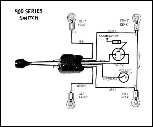
Here's the basic wiring diagram for the type of turn signal system you have. You have to determint if you have the five wire or seven wire system. With the five wire switch you need two sets of rear lights, one for turn signals, one for brakes. With the seven wire switch you only need one set of rear lights because the switch has an internal switch that opens the brake circuits, see the bottom animation:

Hotshot
Joined: Oct 2004
Posts: 15,882
Likes: 88
From: Durham NC
Bob, the only thing I might question is that your diagrams look like they are for a neg ground system? The power would have to come from the neg side if it is a 6V pos ground truck (pre 1956) that has not been converted to 12V neg ground.

Post Fiend
Joined: May 2008
Posts: 7,641
Likes: 21
From: Poway, Ca.
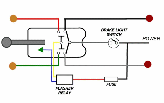
In his picture, it appears that his flasher plug has 3 leads on it. The black wire should be going up to the switch, and the red wire with half the fuse holder should be coming from switched power to the flasher. The two white ones are not connected at all and this is certainly going to be a problem.
I made this diagram when I rewired my truck. It is for the "Everlasting" type switch, but will show you the hook ups in the 7 wire system with three wire flashers, and I think is the same as Bob's 900 series drawing. The colors I show coming out if the switch are the correct colors for that switch but you can see later on down the line I may have switched to a different color. I'm providing this for signal flow.
Here ya go:

If you have trouble reading it go to http://members.***.net/japeterson/49...g_Wiring.ppt#2 There are two like this, one shows all my extra toys and one is generic - you will see the difference!
Or if you like, just send me a PM with your real e-mail address and I'll send you the full size drawing in Power Point.
Good luck
I made this diagram when I rewired my truck. It is for the "Everlasting" type switch, but will show you the hook ups in the 7 wire system with three wire flashers, and I think is the same as Bob's 900 series drawing. The colors I show coming out if the switch are the correct colors for that switch but you can see later on down the line I may have switched to a different color. I'm providing this for signal flow.
Here ya go:
If you have trouble reading it go to http://members.***.net/japeterson/49...g_Wiring.ppt#2 There are two like this, one shows all my extra toys and one is generic - you will see the difference!
Or if you like, just send me a PM with your real e-mail address and I'll send you the full size drawing in Power Point.
Good luck

