When you click on links to various merchants on this site and make a purchase, this can result in this site earning a commission. Affiliate programs and affiliations include, but are not limited to, the eBay Partner Network.
Ideas of what to do with the van's interior were swirling around before any work tearing the old interior out even started. We decided that we liked the overall layout of the old interior and had no plans on changing the seating arrangement. We would keep the large upper cabinet between the section of stock roof above the front seats and the fiberglass high top. We would build a rear upper cabinet above the rear storage area, since additional headroom would not be needed. The basic "footprint" would remain the same, but there would be changes made. Some of my goals would be:
Build everything back more robust and solid
Maximize storage by utilizing cubbies in spaces that were previously void
Update the technology and entertainment systems
Provide a layered lighting experience
Improve the overall travel experience in any way, such as reducing road noise
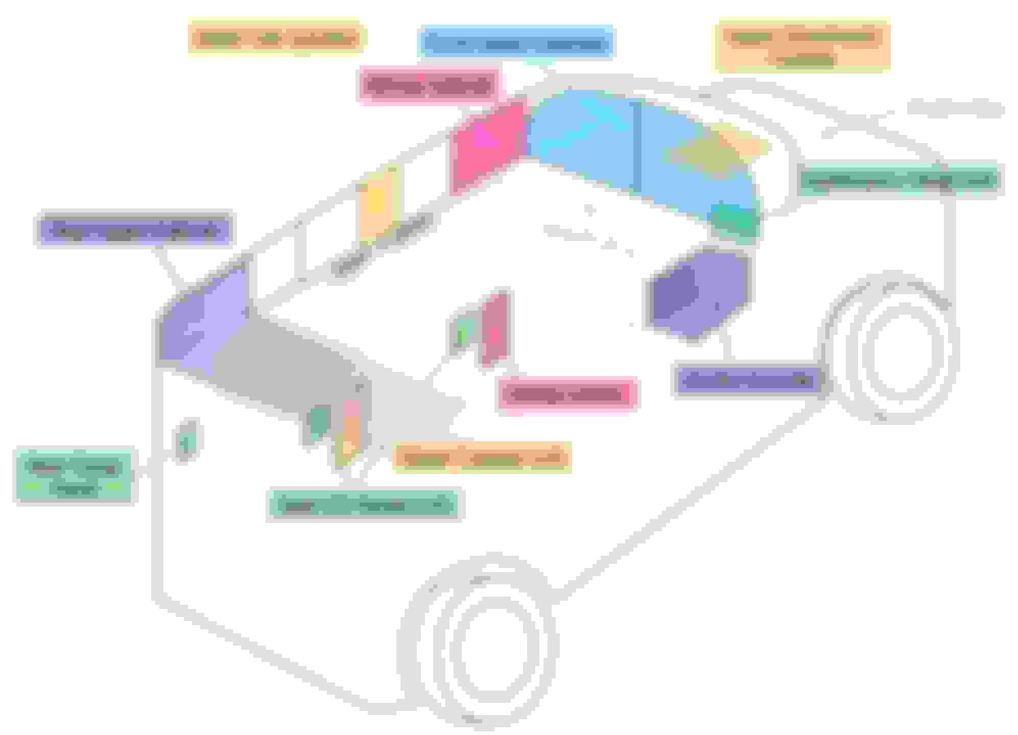
I started planning out the interior by defining spaces and points of engagement. Once these spaces were roughly planned, I could bring the plan into greater resolution by starting to think about things like placement of lights, receptacles, and components.
Here is a rough sketch showing how this plan was taking shape.
Quick sketch showing different spaces of interest
The general plan for these spaces were:
Front Upper Cabinets
This space would be divided in half. The left half would store most of the electronics, such as the battery, DC-DC charger, and inverter. The right side would be a large storage cubby. A flat screen LCD monitor would be mounted to the surface in place of the recessed CRT TV that I removed earlier.
Wiring Cabinet
This space would contain fuse panels and relays. It would be located in one of a bank of upper cubbies that span the space between the front and rear upper cabinets and be found on both sides of the van
Upper (Overhead) Console
A switch panel would control things like lighting and maybe other things. There would also be some storage space for at least sunglasses, if not more
Dashboard / Head Unit
The cheap aftermarket radio would be replaced with a touch screen capable of Apple Carplay and Android Auto. There may be other upgrades to the dashboard
Center Console
I wasn't sure about having a "true" center console at this point, but was seriously considering it. A custom center console would contain charging ports and plenty of storage
Media Center
This would be in the same location as the conversion company's radio and cassette player unit. However, it would hold some slightly newer entertainment technology
Rear Upper Cabinet
Before this was all void space and just had the two rear air ducts. Now it would also include more storage space
Lower Cubbies
A few lower cubbies will fill void space and provide general storage for the middle and rear seats. We were tossing around some ideas that would turn these into more specialized storage solutions, but we leaned towards more simple and universal cubbies
Seat I/O Panels
Each seat with exception to the middle rear bench seating position would have a panel with charging ports of various types and maybe some inputs and outputs to the entertainment system
Rear Cargo Panel
Similar to the Seat I/O Panels in charging options, but no need for entertainment system I/O ports
Upper Cab Junction
Part of the Upper Cubbies, but would contain lots of wiring in a "junction box" so probably not readily accessible
Next up will be the electrical and entertainment system plans�
All these plans of how I would rewire the cabin and other parts of the van were swirling through my head, so I started putting them down to keep everything straight. Here is the electrical plan I eventually came up with. Keep in mind, throughout the later parts of the wiring process I was making a few changes in the field that didn't make it on the drawn plans, so this diagram is mostly, but not 100% accurate. The electrical and audio/visual plan
Some notes on this diagram:
1. For the most part, negative wiring is not shown. Virtually all runs are two wire (positive and negative) and the negative wire goes back to whichever fuse box feeds the circuit. The fuse boxes negatives then run to the leisure battery, which is then connected to the starter battery's negative terminal.
2. Throughout the plans, I use "ACC" to denote Accessory Power - when the ignition key is in either the ACC or RUN position. So basically, anything labeled "ACC" is only powered on when the van is running.
3. Relays are shown with their terminals numbered. Almost every relay is NO, there is one NC and a couple of programmable timer relays.
4. "ACC source" is a wire left during demo that is hot when key is in ACC or RUN position. "door switch source" is a wire left during demo that is hot when any door is open.
5. Not all light fixtures are shown. The lighting circuits are generally simplified and labeled as: d = "dome lights" or cabin lights. This is the primary lighting interior lighting circuit
n = "night lights". This lighting circuit is designed to give soft light, enough to see things in an otherwise dark cabin, but not be too bright as to impair the night vision of the driver.
c = "cabinet lights" These are lights generally controlled by switches or magnetic reed switches to illuminate cabinets or cubbies. The ones controlled by magnetic reed switches will turn on when their cabinet door is opened and turn off when the door is closed. The Heart of the System
12V 50Ah LiFePO4 Lithium Battery ($180)
A "leisure" battery would power nearly everything in the cab. This way, there is separation with the starter battery, so if lights are left on and drain the battery, you can still start the van.
Renogy 12V DC-DC Charger ($109)
To keep the leisure battery charged, it would be hooked up to the starter battery through a DC to DC charger. This charger works for Lithium, Flooded, Gel, and AGM batteries and protects the alternator when charging lithium batteries. The charger is set up to turn on after a 30 second delay after the van is running, the thought being to let the alternator a little time to start before applying this additional load.
10A Battery Charger
This smart battery charger is plugged into a 120V receptacle that is hot when shore power is provided (via a shore plug in the rear right of the van). So when the van is plugged into 120V AC power, the leisure battery will charge.
2000W Pure Sine Wave Inverter with Auto Transfer Switch ($250)
This 12V DC to 120V AC inverter can be activated either by the application of 120V AC shore power or by a switch in the overhead console that energizes a relay which gets its power straight from the leisure battery.
12 Way Waterproof Fuse Block ($19) and 6 Way Waterproof Fuse Block ($14)
There are two fuse boxes to power all the different circuits. The larger 12 fuse block is directly connected to the leisure battery and is always hot. The smaller 6 fuse block is connected to the leisure battery via a relay which is triggered when the ACC source is hot.
Most of the wiring is pretty straight forward, but there are a few circuits and systems that are slightly more complicated, so I'll go over them in detail here.
Cabin Lighting Circuit
The cabin lights are the primary interior lights for the van. They consist of LED puck lights spaced throughout the vehicle as well as some LED strip lights in the ceiling trim.
This circuit is controlled in one of two ways:
1. A switch in the overhead console will manually turn on the lights at any time
2. The lights will turn on when any door is opened if a few conditions are met
Here's a diagram showing the circuit:
The cabin lighting circuit
Manual Control
This method is straight forward. The overhead console switch triggers a relay which sends power to the interior cabin lights
Door Control
This method of control is a bit more complex. There is programmable time-off/time-on relay which is wired up and programmed to pass power from its input DC+ port to its OUT+ and its DC- port to its OUT- port when power is applied to the trigger port. The trigger port is wired up from the door source circuit, so when any door is opened, the relay closes the connection and passes power. I have it programmed to stay energized for 3 minutes after the trigger source power is removed, so the lights will remain on after the doors are closed. Note: the front and side doors are on a factory timer, so even when they remain open, after several minutes, the door source wire will stop sending power and the 3 minute timer starts.
Power (positive and negative) then leave the timer relay and energize another relay. I put this in place to prevent back-feeding the timer relay. I could have used diodes but I didn't have any on hand and I had several extra relays. The next relay is a Normally Closed (NC) relay, so it will pass power until power is applied to the trigger terminal. The trigger terminal is energized by the ACC source circuit, so what this does is when the van is started, it will turn off the interior lights (as long as they aren't manually turned on). Finally, there is another switch in the overhead console, called the "Door Switch" which can be turned off to disable this method of lighting control.
Rear Camera Circuit
I wanted to be able to manually control the rear camera in addition to it automatically coming on when in reverse. I purchased two cameras for the van (front and rear) and a refurbished BOSS BE10ACP head unit with 10 inch floating screen which, like all after market head units I have seen, can be wired up to automatically turn on and show the rear camera when power is applied to one of the ports (usually hooked up to one of the reverse lights). The rear/reverse camera circuit
I modified the typical installation by adding a relay that is triggered by an overhead console switch. Then I added another relay that is triggered by one of the reverse lights. Finally, if either of the relays are energized, not only does it pass power to the camera, it also sends power to the head unit to make it automatically switch to the reverse camera view.
Entertainment System
This can be split into audio and video. The final destinations for video are a 20 inch monitor mounted on the front upper cabinet and optionally, the head unit's 10 inch screen. The final destination for audio is either a pair of sound bar speakers or a series of headphone jacks. The entertainment system
A HDMI switch with audio extractor is central to the system. It accepts 5 HDMI inputs: 4 from various seats and one is from a mini media player computer with USB flash drive full of movies, TV shows, photos, and music. The HDMI switch then sends the HDMI signal to a splitter which then sends it to the monitor and to an HDMI to RCA converter. The converter sends that signal to the BOSS head unit which can then be viewed by pressing the "AUX IN" on-screen button (as a parent, this is to check what is being watched, not to distract from driving).
The audio from the HDMI input(s) is extracted and send via a 3.5mm cable to an audio switcher with volume control ****. This device is located in the overhead console so the driver has control of the volume and where the audio is sent to. The signal can either be send to a couple of speakers, or to the headphone jacks found at most seats.
To start framing the interior I looked to the window trim. I reused the boards that I had removed earlier. I first had to remove the old headliner material from them, then apply my new tan headliner material.
Next, I secured some 2X wood boards throughout that would be anchor points for the rest of the interior framing. I placed a 2x4 between the top of the b-pillars to define the front upper cabinet and a 2x4 between the d-pillars to define the rear upper cabinet Then I attached some 2X boards to the inner skin at the floor-to-wall meeting to anchor the bottoms of the walls and some boards below the window line to fasten the top of the lower walls to.
I then cut out the basic wall framing out of plywood sheathing. This utilitarian material would be the foundation and later be covered by decorative wood or headliner material. The lower wall panels had cutouts for the seat I/O panels, cubbies, and the one factory speaker behind the driver's seat. Getting the "pillar" framing for the upper walls took a bit of work, even using the old boards that I demoed as templates.
Before installing this framing, I placed some thick aluminum flashing below where the framing would go, and strategically spread throughout the floor and inside the door panels. This is to stiffen the sheet metal and reduce the "tinny" sound it tends to have. I would later be laying down thicker foam-based sound deadening, but that comes much later. There are various products designed especially for this, but I chose just to use locally available flashing from the big box store.
Finally, I made the basic form for the upper front cabinet (as seen in photo above). Here, you can see that space divided in half, the left half will be for electronics, the right for storage.
All the cabin wiring runs off the 50Ah leisure battery that will be above the driver's seat, but first I needed to run the 6 gauge positive and negative wires from the starter battery to the front upper cabinet. While it would be a shorter cable run from the starter battery to the right side of the front upper cabinet, most of the interior wiring would be running along the left wall above the windows, so I decided to put the "guts" of the system on the left side.
Here's the wire path I chose to use:
From the starter battery, the wires enter the cowl space (where the windshield washer hoses run). There was a perfectly placed rubber grommet nearby that I could use. It then runs across and from the cowling void, enters the left front fender through another existing hole. From the fender, it enters the cabin space through another existing hole near the parking brake foot lever. It then follows the parking brake cable down into the driver's foot well, then up behind the b-pillar trim and into the upper cabinet where the DC-DC charger and battery would be located.
At the starter battery with inline fuse holder waiting to be installed
Running through the cowling space to go across engine bay
Pulling cable through fender and getting ready to enter cabin
Wiring running with parking brake cable in driver's step well
Up the left b-pillar and into the primary wiring closet with the DC-DC charger and leisure battery
On the starter battery end, I added an inline fuse holder on the positive cable. I ended up using a 50A fuse after some trial and error when testing different charging settings on the DC-DC charger.
With the primary electrical source in place, I began running all the wiring and cables throughout the cabin. The top of the left wall, tucked in a handy cavity between the fiberglass high-top and the top of the factory wall turned out to be an ideal place to run wires. Wiring needed for the lower left wall would then either go down the b-pillar or c-pillar. Wiring for the right side of the van would go to the c-pillar, then up and across the ceiling, then either down the right-side c-pillar or along the top of the right wall to its destination.
Here's a quick and very basic diagram to try to illustrate the basic wiring schematic:
I tried to keep the wiring neat and tidy and taped bundles together and put them in wire loom where needed. I also had color coded most of the wiring which helped identify it at a glance. At either terminal end, I would add a label to identify which circuit the wire was a part of.
Wiring for the future center console ran down the left b-pillar and along the floor behind the driver seat. The wires were spread out a bit to make them flat and taped down. They would then go through a custom bracket I made to mount the center console to the floor of the van. I left those wires extra long for now, but would eventually terminate them in a 12-wire plug so the future center console could easily be removed whenever the dog house needed to be removed for engine work.
I didn't get many photos of all this work which is unfortunate, but here's a photo of a curious bystander who popped in from time to time to inspect my work:
Electrical inspector shows up on the job; he's a little nutty if you ask me
As most of the wire had been run I needed to turn towards the upper cubbies because one of these cubbies would house the HOT and ACC fuse boxes as well as a bank of relays. The rest of the cubbies would be bonus storage space that was wasted by the conversion company.
A 2x4 cleat running the length between the front and rear upper cabinets would form the foundation for the upper cubbies. I cut out a section where the cleat runs past the b and c-pillars to allow space for the wiring running up and down those areas. Finally, these cleats defined the space for the upper cubbies.
Now on to the upper cubbies themselves. Each side of the van would have 4 cubbies with a vacant space in the middle for wiring space. Each side would be constructed as one unit with a plywood floor and 3 layers of plywood for each divider between cubbies. The reason for 3 layers was that the middle layer was more of a spacer and would be where the ceiling "rafters" would fit into, but I'm getting ahead of myself. Strips of tempered hardboard would run the length of the back of the cubbies to act as mounting points for the headliner material which was used for the cubby backs, sides, and floor. Each cubby has unique dimensions to fit the curved shape of the fiberglass high top, so that took a bit of effort to get to fit well.
Here's a photo showing the back side of one of the cubby units. You can see that I prewired each cubby with a small LED light. The lights for each bank of cubbies would be controlled by a switch mounted to the middle of the unit.
The back of one cubby unit showing its construction and lighting
Here you can see the cubbies and 2x4 cleats on each side of the van. In this photo, the cubbies do not yet have their backs and tops.
And here is a view of the left side upper cubby unit. You can see how each cubby has a unique shape to fit the ceiling. You can also see the gaps between the dividers that will be used for the ceiling joists/rafters.
The left bank of cubbies in place
With the upper cubbies in place, I could then install the fuse boxes and relays and terminate the wiring.
The left front cubby houses the fuse boxes and bank of relays
It was June and with the summer heat cooking us, we noticed that the AC in the van wasn't working. I would need to address this while I had easy access to the rear HVAC unit and refrigerant lines running through the lower left wall...
It gets hot and humid during the summer and we also wanted to use the van as a road trip vehicle which would take it all over the US including the south west during the summer, so having working AC is very important. Unfortunately, at this time, I found out that the AC was not working. When set to AC or MAX AC, the compressor would never kick on. So here's a summary of what I did to troubleshoot and address the issue - please note that I'm not an AC tech by any stretch of the imagination so view this as "entertainment only."
Testing the Compressor
There are many reasons the AC compressor may not turn on, but before I got into expensive and time consuming repairs, I wanted to test the compressor itself. After a lot of research on the AC system, I found out that this van has a very basic control system. I was searching for relays and fuses but this year of van had none for the compressor (at least in either of the fuse boxes).
So then I decided to try jumping the low pressure switch. This switch's harness is mounted to the inner fender next to the battery. I disconnected the switch and used a bit of wire to jump the terminals on the harness side while the van was running with AC controls turned on. I could watch the AC clutch engage and compressor come on when the pins were jumped, so that told me that the compressor clutch was at least good and that a lack of refrigerant was likely.
Refrigerant
I purchased one of those DIY AC recharge kits that had dye included in the refrigerant. I charged the system with a couple of 8 oz cans and the compressor started to short cycle. I let it run long enough to let the refrigerant time to cycle throughout the system, then I checked everything with a UV flashlight searching for dye indicating leaks. I checked everywhere I could in the engine bay an then followed the coolant lines that lead to the rear HVAC unit. Finally, I scoured the rear unit. I didn't find anything indicating leaks.
Even though I couldn't find any leaks, I was finding out the limitations of the simple kit I had, so I ended up purchasing a manifold and vacuum pump kit off Amazon for about $120. With a real manifold, I could get accurate pressure readings on both the low and high ports.
So with a manifold, here is what I found (all readings are taken when AC compressor is running):
Initial reading: 15/115 - this was very low
After adding a total of 24 oz of refrigerant and outside temp was 88* @ 50% humidity: 25/150
After adding another 24 oz (48 oz total) with 90* @ 48%: 30/190. Still low
After another ~12 oz (60 oz total) with 86* @ 57% humidity and got 45/199
At this point I had added about 60 oz of refrigerant, which is the total for this system (44 OEM plus 16 for aftermarket rear unit).
With a vent thermometer I was getting 40* and the compressor was no longer short cycling. I don't know why the system was apparently empty, especially since I couldn't find any leaks, but I would keep an eye on everything throughout the summer and was prepared of doing more substantial repairs if necessary. (note: almost 2 years later and the AC is still working)
Rear HVAC Unit
This conversion van came with an aftermarket evaporator unit (a ProAir 1100 or similar) that provides rear heat and AC. The blower fan made a lot of noise as it sounded like the fan blades were contacting the fan housing. While I still had ample access to this unit, I decided to see if this could be fixed.
A breakdown of the rear HVAC unit
The fan easily comes off the unit without having to disconnect any coolant or refrigerant lines (about the only thing you can do to this unit without removing the lines). When I took the fan assembly apart, I found that the fan blade shaft had some play that caused it to rub the housing. I searched for replacement parts but it looks like these were about 10 years out of production and nearly impossible to find or way too expensive for this budget build. So instead, I used a couple of fuel injector washers I had from a recent intake manifold gasket replacement I had done on my 2005 4.6L F150 as spacers on the fan shaft. A bit of shade-tree engineering, but it worked and the fan was now quiet.
Part of turning the van's interior color scheme to tans and browns includes painting some of the stock trim and the dashboard. The only stock trim left in the van is from the b-pillars forward. I found some spray paint that I thought complimented the headliner material (based off the cap color at least) and it was on clearance for over half off, so I bought the few cans they had.
I had the a-pillar, b-pillar, and above door trim already pulled off, so after a thorough cleaning, I sprayed each with several light coats and set them aside to cure for a few days. The dashboard would be a different story as I would have to paint it in place.
In preparation to paint the dash, I removed the dashboard insert panel and the vents. I then covered up anything that I didn't want overspray on, though at this point with the interior mostly bare, it didn't take long. I was happy to no longer have the sea of gray.
With the dash insert panel removed, the plan was to give it a faux wood finish. I first removed the cigarette lighter and slightly enlarged that hole to accept a USB panel. Then I made my first attempt at applying an adhesive vinyl to the panel. After a couple of failed attempts, I realized I wasn't going to get the result I wanted with all the curves and complex shapes; I just couldn't get the vinyl applied well enough.
So I pivoted to plan B: I spray painted a base color (terra cotta) and let that paint fully cure. Then I used a mahogany gel stain and dabbed it on with a bundled up plastic grocery bag which gave a nice base pattern and texture. Finally, I brushed the gel stain on to simulate wood grain. After letting the gel stain ample time to cure, I sprayed the whole thing with a thick clear coat. I personally think it turned out really well. It is obviously not wood, but the color and visual texture fits the interior very well and, IMHO, it is a huge upgrade over the matte black. It also was inexpensive as it cost about $14 in spray paint and I used a gel stain I already had in stock.
The dash insert panel painted, stained, and clear coated
The dashboard partially reinstalled
With the dash reassembled in the van, I went ahead and installed the BOSS head unit and wired its USB inputs to the USB panel that replaced the cig lighter. I also found a center console from a newer van, but would later ditch this in favor of enlarging the plans for my DIY center console.
Before and after
During this visual upgrade, I took advantage of having the pillar trim off and addressed a glaring omission from this van: a complete lack of grab handles. More on that in the next post.
Our 1999 Econoline did not come with factory grab handles to aid in ingress and egress. I definitely wanted to add these handles to take stress off the steering wheel which is often tugged on when the driver is climbing into the seat.
I know that grab handles from later years are available, but after not finding anything nearby or for a reasonable price, I decided to turn to something I did have plenty of: 3/16 x 1 inch mild steel and flux core welding wire.
I was very conscientious about making sure the foundation of the grab handles would be secure so that the sheet metal that they attached to wouldn't, over time, be damaged. In order to ensure a solid base, I would spread the load over as much sheet metal as I could.
Front Grab Handles
Starting with the a-pillars, I found two flat sections of inner sheet metal positioned in perfect spots for grab handle mounting plates. So I cut some lengths of 3/16x1 steel to fit these sections, drilled 4 holes in each plate, then used those holes to transfer hole locations to the a-pillars. Then I drilled and tapped those holes in the a-pillars (everything got Fluid Film sprayed to protect the newly exposed metal).
Tapping the mounting holes for the base plates
Next, I welded a nut to the center of each plate. This would be the mounting point of the handles. I then "dry fit" the plates. So far so good.
A single plate test fitted to the a-pillar
To prevent the trim from being crushed when the grab handles are tightened down to the base, I added some piping that surrounds the nut and would extend out to be just proud of the trim. The grab handles would tighten down to these pipes, thus sparing the plastic trim. A little cleaning and black paint and the a-pillar bases are done.
Base plates finished
Trim reinstalled
The a-pillars are now ready for the actual handles. I mocked up some handles with cardboard to test size, shape, and position.
Searching for shape with a cardboard template
When I got what I wanted, I transferred these to the metal bars. Each handle would be made from 3 pieces of mild steel welded together, then two holes would be drilled to accept the bolts that would mount the handles to the bases that I just made. Once again, after the handles were welded up, ground, and cleaned, a couple coats of black paint finished them up enough to installation. The plan was to wrap these metal handles with some combination of wood, foam, and leather, but even as of this writing, I haven't gotten around to it. They work as-is and are very handy.
Grab handle welded up and test fitted
Finished a-pillar grab handle (driver's side, passenger side identical)
Side Grab Handle
I also wanted to add a grab handle in the b-pillar behind the passenger seat to aid passengers getting in and out through the side barn doors. The general process would be similar to the a-pillar handles, but there were enough differences in mounting to require some additional engineering.
The biggest hurdle with the b-pillar is that the inner sheet metal is not flat, it curves gently, so a flat bar will only contact the sheet metal at the top and bottom of the bar. To maximize the contact patch, I would have to take two metal bars and bend one to match the curvature of the pillar, then weld it to a flat section of metal bar, making a shallow "D". A small spacer in the middle would help keep the base's form. Then two holes would be drilled through both plates and into the sheet metal. However, this time, the sheet metal would not be tapped, since there was just enough space to get my hand, a washer, and a nut onto the backside of the mounting bolts.
Finally, I used coupler nuts, welded onto the base, to act as both the nut and spacer which the grab handle would mount to.
b-pillar grab handle base plate installed
With the trim reinstalled, it was just a matter of making another cardboard template and transferring that into the metal bars. This handle was a rectangular shape with 4 sides, not a "C" shape like the a-pillar handles.. I did this so that the mounting holes could be drilled into one of the long sides, but off center. This way, I could flip the handle over so it could mount higher or lower. Unfortunately I don't have any good photos of this handle, so I'll try to get one later.
b-pillar with trim reinstalled
I am very happy with the outcome of this project, and for minimal cost (though a fair bit of work), the van now was 3 very sturdy handles.
Rafters
Continuing with the framing of the van's interior takes us from the walls to the ceiling. I made a series of rafters that would span the width of the van and attached into the upper cubbies. These rafters would support a board running the length of the van that would house lights and be an anchor to the main ceiling panels.
Front Upper Cabinet
Moving on to the front of the van, I framed out the front upper cabinet out of a piece of plywood (after making a template to get the dimensions correct). Before attaching this plywood to the subframing, I dressed out the right storage cubby with headliner material and added the mini LED lights that I used in the upper cubbies, night lights, and other places throughout the interior build.
I used these mini LED lights throughout the van build - they put out just enough light for small spaces
The plywood for the front cabinet includes openings for the left and right cubbies. There is also a cut-out that will be located behind the monitor that serves as a pathway for HDMI and power cables and will also have some small fans for adding some air circulation into the left (electronic) cubby.
Front Headliner
With the framing done for the front upper cabinets, I could cut a piece of hardboard to fit and adhere headliner material to it. A hole was cut for wiring the overhead console and the whole thing is screwed to the framing in areas that will later be covered by trim. I marked out the area where the overhead console will attach through the headliner into framing with some blue painter's tape.
Spine
The board running the length of the ceiling between the front and rear upper cabinets, which I refer to as the "spine" is secured to the rafters and to the front and rear upper cabinet framing. A section near the front is cut boxed out and has an opening to house and provide access to a pair of fiber optic light sources that will power the star field lights in the ceiling. Additional holes for cabin and night lighting were drilled along the length of the spine board.
With everything being covered here, I only have 2 photos which show only the front couple of rafters and section of spine. I was working hard to get things finished and didn't always take the time to document everything as well as I should have.
At this point the framing is nearly done, just a few areas to complete. Having the ceiling framed out also allows the next steps in finishing the interior, as I'll be working top down. So the overhead console and ceiling panels are next on the to-do list.
Since I didn't have any good photos of the b-pillar grab handle earlier, I took some the other day to complete that post. It was a bit harder to get a good photo since now the front passenger seat and seat belt are in the way whereas before they were removed from the van when I was making and installing the grab handles.
From the conversion company, the van had a small bank of switches in the overhead console location. One of the things I didn't like about it, other than half the buttons not working, was that there was no storage for things like sunglasses. When planning the overhead console build, I knew I wanted to incorporate the following features:
switch bank for lights and other features
house primary cabin lights for front seats
night lights to illuminate from seats without disrupting night vision
audio switcher with volume control and mute button
storage
lighting for storage
The console's finish materials would be a combination of stained wood and headliner material. Once again, I didn't get any photos of the build process, so finished photos will have to suffice.
The Switch Bank
I wanted the overhead console to be the "command center" for several systems of the van. From here, the driver or passenger could control the following:
Door Switch
The door switch controls whether the cabin lights come on when a door is opened.
Cabin Lights
This switch lets you manually turn on the cabin lights at any time.
Night Lights
This switch turns on the "night light" circuit which provides soft light strategically aimed throughout the interior.
Star Field
This turns on two lights mounted above the ceiling "spine" board which illuminate the fiber optic star field in the ceiling headliners.
Reverse Cam
This manually turns on the rear or reverse camera so it can be viewed at any time (that the van is running) and not just when the van is in reverse.
Inverter
This switch turns on the 2000W 120V AC inverter. By default, this will also turn on the monitor, media player mini PC, HDMI switch, and front sound bar speaker. This is the one the kids usually ask for us to turn on!
The switch bank is composed of these 6 switches which I wired up so that when ACC power is on, the switch lettering is illuminated (in green). When a switch is turned on, then its icon is also backlight with a green LED. The switches themselves came from Amazon. I found lots of pre-designed switches, but didn't find designs for everything I wanted. What I did find was an Amazon store that let you customize your switches. My wife agreed that it would be worth the increase in price to get exactly what we wanted. So I came up with the icons for each switch and submitted my order. Each switch was about $17, but when they arrived, they were exactly as I designed and we both loved them.
The switch bank
Audio Controls
Moving back from the switch bank is the audio switcher with volume control. I wanted to be able to control the volume of the sound bar speakers/headphones so that if the movie or show that the passengers (kids) were watching was too loud, I could turn it down.
Storage
There is ample storage for several pairs of sunglasses or some other smaller items. I like having lots of storage cubbies, even small ones, as it helps organize the clutter, especially on long road trips, and that is what this van was primarily being built for.
Now that the framing for the ceiling was finished and I was already finishing up the ceiling above the front seats, it was time to move to the main ceiling panels. These panels needed to go in before I made and installed the trim and face frames for the upper cubbies and ceiling "spine" - as these parts would help support the ceiling panels and hide their fasteners.
The ceiling would be split into two panels - left and right - separated by the spine running the length of the ceiling in the middle of the van. While the panels would be wrapped in headliner, my wife asked how hard it would be to add star lights. It was clear that these panels would take a bit more work, so I purchased two fiber optic kits and mounted the light units in the center spine framing.
To install the fiber optic in the panels, I first found a "star map" and marked star locations on the back of the panels. This way, actual constellations could be found in the headliner.
Planning the star locations on the back of one panel
I experimented with some ways of creating holes in the panel for the fiber to pass through. I ended up drilling tiny holes and poking the fiber through, then using flush cutters to cut the excess off. Some fibers I passed through the tempered hardboard panel, but did not pierce through the headliner material. My thought was that these would be dimmer and add some depth to the starfield. In reality, it was only partially successful. I did run into issues with headliner material sometimes "blowing out" when drilling the holes, even when using scrap wood to back the drilling. The headliner material also ended up having small imprints throughout; while this was not too noticeable in daylight, low angled lighting sources accentuated the bumpy surface.
To secure the fiber in the panels, I put a dab of glue on the back of each. I then bench tested each panel by just using a strong flashlight to illuminate the fibers.
Bench testing one of the panels before installation
When each panel was completed, I installed them in the van, carefully routing the bundled fiber to the head units. I secured the panels with screws along the central spine framing and to a backing strip next to the side cubbies. These would later be covered by additional finished wood trim.
The fiber optic kits come with remote controls where you can control a number of things including the color. So here are some photos of playing around with the settings. The star lights are hugely popular with the kids and my youngest insists that she gets the remote to change the colors as we drive.
Both panels installed First panel installed and showcasing the stars
With the ceilings done, it is time to start moving down the walls with finish materials...
Both ceiling panels were installed and it was time to finish the ceiling "spine". Like all finished wood in this build, I used some maple I had left over from a furniture build. All this maple was rough sawn, so I had to joint and plane it down, then I used a mahogany gel stain to darken its color. Finally, a wiping varnish (50-50 oil poly and mineral spirits wiped on) protected the finish.
This central work has cabin puck lights, mini LED night lights, and hides LED strip lights running on both sides.
Star Field and Night Light circuits on All the ceiling lights on - cabin, night, and star
Before trimming out the upper cubbies, I needed to finish the gap between the top of the wall framing and the bottom of the upper cubbies.
I installed strips of tempered hardboard to server as a backer for my foam-backed headliner fabric. The plan was simple: attach the headliner material to the 2x4 cleat below the upper cubbies and contour it to the top of the wall framing. The headliner could go lower on the pillar framing and be surface stapled since these areas would later be covered, but where the headliner met the window trim, it would be tucked up between the window trim and top of window framing.
Headliner material stapled to cleat and ready to wrap down It looks much better with the bare metal hidden
One area of concern was the upper seat belt mounting points. I ended up cutting and bending the hardboard backer so that the seat belt mounting bolts would still properly mount, and the headliner would just need to be stretched and massaged to fit the odd contours.
At the rear of the van, I also applied headliner material around the rear door opening. The edges wouldn't need to be perfect as they would later be covered, so at this point it looks a bit messy, but when finished, it would look a lot better.
My summer is about to get a lot busier, so this will be the last post for a while. I welcome any feedback and constructive criticism (although the build is much farther along than where this post ends). The next few posts will show more finish work on the walls before moving to the floor. Thanks for viewing up to this point!
Your craftsmanship and fabrication skills are impressive.
For those of us who more fabrication-challenged, grab handles can be salvaged from junkyards and installed with rivet nuts. Handles and trim pieces are less than $30 each. It helps to live in a state where there are millions (literally) of junked vehicles so sourcing parts is relatively easy.
Front handles are from an Econoline van. Rear handle is from the back seat of an F250. I couldn't figure out a clean way to install a B pilar handle but the OEM front seat has a handle on the back that kinda helps.
This Hennessey Takes the Expedition Tremor's Off-Roading Capability to the Next Level
Slideshow: The VelociRaptor Expedition gains a lift, upgraded suspension, Brembo brakes, and trail-ready equipment while retaining the stock 440-horsepower EcoBoost V6.
Rezvani's Latest Post-Apocalyptic Monster Is a Ford F-150 Raptor Underneath
Slideshow: Called the Fortress, the 850-horsepower pickup combines Raptor underpinnings with military-inspired features, survival equipment, and a starting price of $285,000.