When you click on links to various merchants on this site and make a purchase, this can result in this site earning a commission. Affiliate programs and affiliations include, but are not limited to, the eBay Partner Network.
Hi guys, struggling to figure out the power locks on my van. It’s a 2003 wiring in the rear, with a rke module but a 2005 on the door switches.
I can’t seem to get any life out of the pdl no matter what I do. My wiring diagrams say bk/wt power all the time to the switch from fuse 2.5. But there isn’t power there. I tried a jumper to power it but still nothing on the switch.
anyone know how the actuators actually fire? Mine looks like pk/bk and pk/og off the actuator.
I bought an aftermarket rke module and would love to get it installed by bypassing the original rke.
Well maybe you guys can help with Id of the components.
I think I have the rke module in the b pillar but don’t have the vsm module in the pass a pillar. Here are some photos. The door lock switches line up with 2005 diagrams. The van is a 2005 e350 v10.
The first pic is a 2003 RKE module. The 2005 should (as I think you know) have a security module in the passenger kick panel but yours seems to have the 2003 RKE module in the B-pillar (which is where it should be on a 2003). The black connector is C3140a and the gray connector is C3140b.
The second pic appears to be the driver's door switch and I think the connector with the screws is C508.
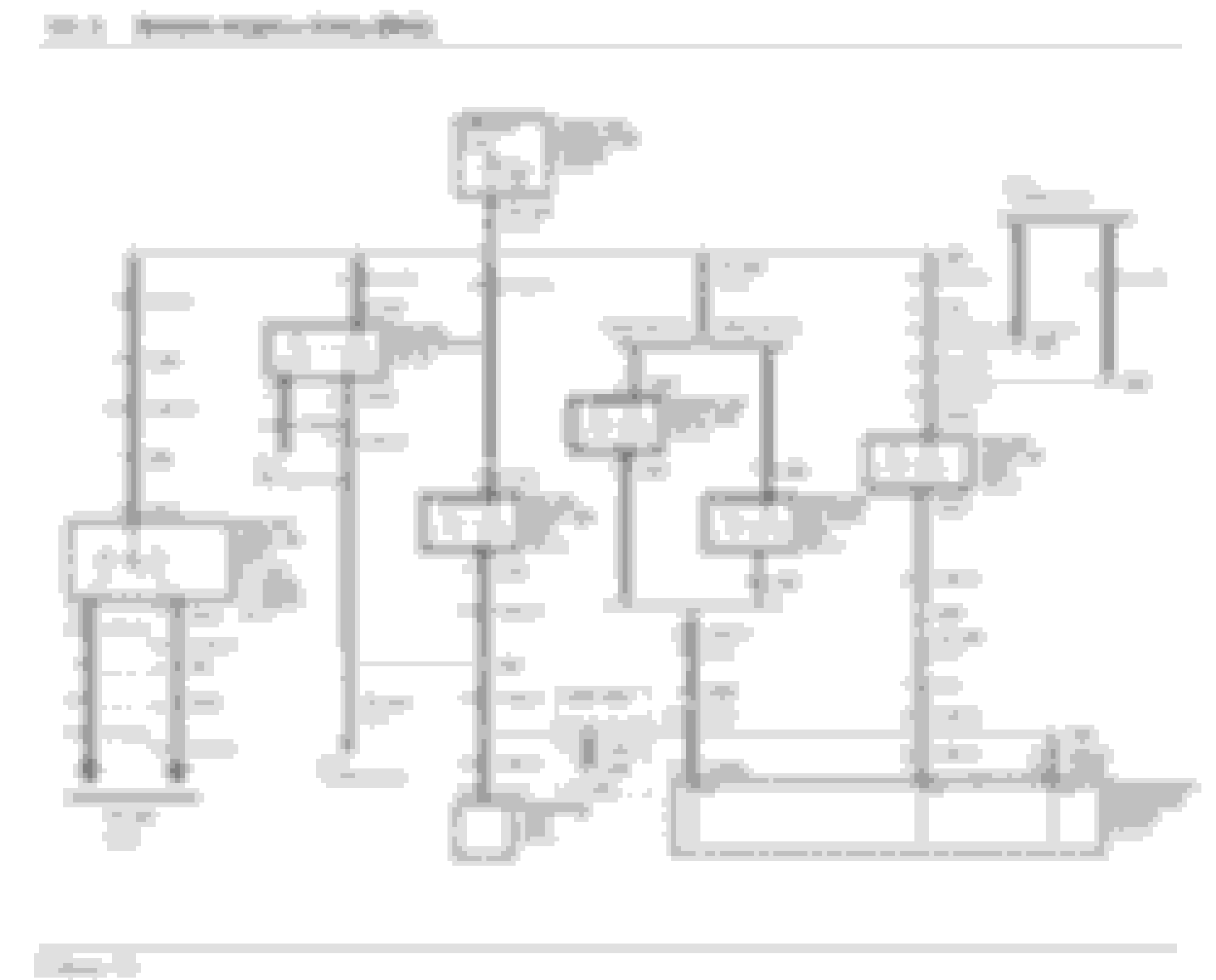
I have attached the pin outs for C3140a & C508. The Service Manual doesn't have a pin out for C3140b.
I've also attached the wiring diagrams for the RKE system.
Pin out and wiring diagrams all from the 2003 manual.
Are you overthinking the door locks?
A test light will make them operate from the switch wiring on a powered system
Use the correct EVTM for your van and trace the circuit power wiring to the drivers switch
Broken wires through the door accordion come to mind
Leave the RKE out of it for now
With a broken wire, or no power the RKE will not work anyway
I have been trying to follow the power locks diagram. It’s not getting constant power to the bk/wt. that wire switches to pk/lg at the door connection. Fuse 2.5 is fine and has power.
I don’t know how to jumper the wire to function the locks. I tried to jump power to bk/wt but still no function
Using a jumper wire
Provide B+ to the black with white wire at the back of the lock switch connector in the drivers door
Then see if the door locks work
Listen for sparks while that wire is powered up and you move the door wiring around through the accordion
Try this
Reverse power a test light
Means hook the alligator clip to power B+
Then probe the back of the lock switches with the point and the locks will lock and unlock
Provided the actuators work
Ok thanks I will try this and see how it goes. I have powered up the bk/wh but still nothing.
I feel like I need to power up the constant bk/wh and then add a signal power to the output?
I have checked continuity from switch to door connector in the a pillar and it’s ok.
I believe there is a LOT of confusion in this thread... Ford used four different methods of controlling the door locks in the years I have Service Manuals (SM) for (1997-2010):
Remote Keyless Entry (RKE): 1997-2003 (and likely earlier) - RKE module in the driver's B pillar
Vehicle Security Module (VSM): 2004-2008 - VSM module in the passenger kick panel
Smart Junction Box (SLB): 2009-2010 (and likely later) - Door lock functionality in the SJB
Power Door Locks (PDL): 2008 and earlier - Hard wired door lock control with no module involved. This was used on vehicles without remote.
From 1997 to 2008 PDL was used in all vehicles supplied without remotes while RKE or VSM was used on vehicles with remotes. See above for dates of RKE vs VSM.
In 2009 all door lock functionality was integrated into the SJB whether or not a remote was included. Perhaps these years were not supplied without remote.
The SM has two separate sets of wiring diagrams for door locks from 1997-2008; one for PDL and one for the remote capable vehicles (RKE or VSM). Some suggestions such as introducing power at the switches may not work on RKE or VSM equipped units although it's a good test for PDL systems.
To add to the confusion, the OP has a 2005 which, according to the SM, should have a VSM but they have a RKE as evidenced by photos and its location in the B pillar.
I'd suggest unplugging the module and testing based on the wiring diagrams in my post #4 by:
Test for power and ground at the respective power supply pins
Test for power at the respective pins when the switches are actuated
Introduce power and ground to the proper pins and see if the actuators operate
This will help narrow down if the issue is in the power, switch or actuator circuits.
Mind you 'Strayhound' my '98 E150 uses a different RKE module but in my bench testing I found one partially melted Relay and no less than found Capacitors were outside of specification. I've since regained partial recovery but upon further study I've learned that those damnable Chinese counterfeits have been down to Component level. Once the weather warms I'll get into this again and get my Components from Digikey, Mouser or some other reputable US firm.
etinpa provided some excellent clarity on the configurations. The problem seems to be we don't know how this van was built and/or modified. OP said this was a "tour bus" so anytning is possible.
The other question is: is it a 2003 or 2005 factory build. Is it a cutaway?
etinpa has a good instructions for troubleshooting. But I would want to know if this van was wired for standard power locks or RKE or VSM module.
The wiring on the master switch matches a 2005 with power locks only. But has this wiring been modified...maybe to work with a 2003 RKE?
2005 w/power locks: pin 3 on the master switch connector must be 12V always (BLK/WH wire).
2005 w/VSM: pin 3 on the master switch must be GND always....AND pin 4 must be 12V (from the VSM) and goes to GND when the button is pressed. BUT if someone wanted to use a RKE pin 4 will be 0V and go to 12V when the button is pressed, the opposite operation from a VSM.
My guess is there have been some modifications so it may be necessary to ring out each wire at the RKE and master switch.
Thanks guys, it’s certainly confusing. I have tested the rke input voltages and they are present. I have not tried to connect it and test output voltages.
I also don’t understand if I do have rke, which I don’t have any remotes for, are the pdl switches still supposed to have bk/wt hot all the time power? Because it’s not.
my end goal is to get the pdls to function by the switches and then tie in an aftermarket rke.
This Hennessey Takes the Expedition Tremor's Off-Roading Capability to the Next Level
Slideshow: The VelociRaptor Expedition gains a lift, upgraded suspension, Brembo brakes, and trail-ready equipment while retaining the stock 440-horsepower EcoBoost V6.
Rezvani's Latest Post-Apocalyptic Monster Is a Ford F-150 Raptor Underneath
Slideshow: Called the Fortress, the 850-horsepower pickup combines Raptor underpinnings with military-inspired features, survival equipment, and a starting price of $285,000.