When you click on links to various merchants on this site and make a purchase, this can result in this site earning a commission. Affiliate programs and affiliations include, but are not limited to, the eBay Partner Network.
I am following this with interest. I have a 99. The RKE has failed (I know this because I had it connected and with slight pressure on the PCB various things would go off). I wanted to find an aftermarket RKE to "plug" into the existing wiring harness. Looking for (a) recommendations on the aftermarket unit, and (b) wiring diagrams that will explain how the existing system functions. Also, it seems some of the aftermarket units don't have their own relays on the PCB, so you have to install relays separately. The Ford RKE does have relays (six of them). So, to keep things simple I'd like an aftermarket unit with relays built in.
So, if the OP or any of the others posting here could supplement with that information, I know I would appreciate it. I imagine that there are several of us lurking here would would like to know this information.
Thanks.
I haven't purchased an aftermarket remote system yet. Too much on my plate at the moment. I did end up buying a OEM Service Manual with schematics though. It clarified some things for me, especially what you said about the relays. My Van did not come with RKE, but does have power door locks. I've read there are aftermarket systems that will tie right in, to the passenger door lock switch. I was hoping someone had done this and could give a better detailed install brief. Sigh.
If you have a factory original RKE and its seeming ly failed there are numerous automotive module repair facilities to be found with a simple Google search. I stumbled across two or three outfits just this morning: Specialized ECU Repair, Pelican Parts and an outfit called Systems Consulting. Mind you those seem to be more geared towards higher performance European brand modules but they'd be a good starting point.
Some have had good success dismantling their own RKE's, finding a capacitor or two needing replacement and repaired them---no real reports back on their long term results so that that for what its worth.
Originally Posted by Teamtazman
I haven't purchased an aftermarket remote system yet. Too much on my plate at the moment. I did end up buying a OEM Service Manual with schematics though. It clarified some things for me, especially what you said about the relays. My Van did not come with RKE, but does have power door locks. I've read there are aftermarket systems that will tie right in, to the passenger door lock switch. I was hoping someone had done this and could give a better detailed install brief. Sigh.
Not sure what more info I could have posted to help you---as I said earlier an aftermarket alarm supplier will have their own installation procedures so you're on your own as far as DIY installing.
Hmmm it hadn't occurred to me that my on again off again factory RKE could be fixed by an aftermarket kit. Maybe once unemployment kicks in (I applied in March) maybe I'll get one of these.
Just purchased a 98 E350 Extended Club Wagon V10. It has power door locks installed, they work fine. Would like to add remote keyless entry. I do not find the module behind the B pillar as others have suggested. Has anyone added an aftermarket keyless entry system, if so, which one and where did you connect the wires on the vehicle? I see online these systems are pretty cheap. I would like to open the doors with a remote instead of using a key all the time. Not interested in the alarm/siren stuff. Thanks for the help.
Hi, I have a 1998 E350 extended van with 5.4l V8. I am the second owner and I got it in early 2000's. It came with an aftermarket Bulldog Security RKE installed in the passenger door behind the panel. It was connected using the Type "C" door lock wiring. My old bulldog security RKE died and I purchased a generic one on Amazon and it was very inexpensive but very well made. So far I am very impressed with it and the remotes have a quality feel. I am currently in the process of replacing the Bulldog Security one in the door panel. The price was $18 until a few days ago and now it is up to almost $28. Here is a link for Amazon
Hi, I have a 1998 E350 extended van with 5.4l V8. I am the second owner and I got it in early 2000's. It came with an aftermarket Bulldog Security RKE installed in the passenger door behind the panel. It was connected using the Type "C" door lock wiring. My old bulldog security RKE died and I purchased a generic one on Amazon and it was very inexpensive but very well made. So far I am very impressed with it and the remotes have a quality feel. I am currently in the process of replacing the Bulldog Security one in the door panel. The price was $18 until a few days ago and now it is up to almost $28. Here is a link for Amazon https://www.amazon.com/gp/product/B0...?ie=UTF8&psc=1
Thanks! I'll check this one out for sure. It looks like what I'm looking for. Reviews on Amazon talk about the instructions for the wiring are worthless. Would you share any tips or wire colors? I know you mentioned the "C" wiring pic, just curious if theres any more tips. Thank you again
Hi, I have a 1998 E350 extended van with 5.4l V8. I am the second owner and I got it in early 2000's. It came with an aftermarket Bulldog Security RKE installed in the passenger door behind the panel. It was connected using the Type "C" door lock wiring. My old bulldog security RKE died and I purchased a generic one on Amazon and it was very inexpensive but very well made. So far I am very impressed with it and the remotes have a quality feel. I am currently in the process of replacing the Bulldog Security one in the door panel. The price was $18 until a few days ago and now it is up to almost $28. Here is a link for Amazon https://www.amazon.com/gp/product/B0...?ie=UTF8&psc=1
For that price I'd buy up to three of them in case they're not long lived. Before I bought something like this though I'd want to see the installation instructions and/or wiring diagram first. I am guessing integrating it into an existing van with factory PDL's would also require a factory wiring diagram for that system.
I'd also NOT install the main device anywhere but inside the body, NOT in any door---they're just too prone to leaking and/or allowing moisture inside whereas a location inside the body would be a bit more dry.
Yesterday I changed my plans for installing it in the passenger door like my old BullDog RKE was. Thanks JWA!!! I have found a place to install it behind the drivers side rear cabin accessory trim panel. I opened the panel and confirmed I have no factory RKE cables connectors or wiring harness. The service manual for the van shows only the factory RKE in this area and/or the Memory Lock Module. I did find a single unlabeled connector that was right by behind B pillar. It is a factory connector C330 to plug into a Memory Lock Module. In the absence of the Memory Lock Module they install a wire on the plug to route the lock signal to a wire running over the side door actuator. I have the swinging side doors with a power lock. Connector C330 has all the wiring for a door lock except the physical lock and unlock switches.
The cable going into the connector C330 has:
1. Battery
2. ground
3. lock signal
4. unlock signal
5. lock signal wire to the side swinging door lock actuator.
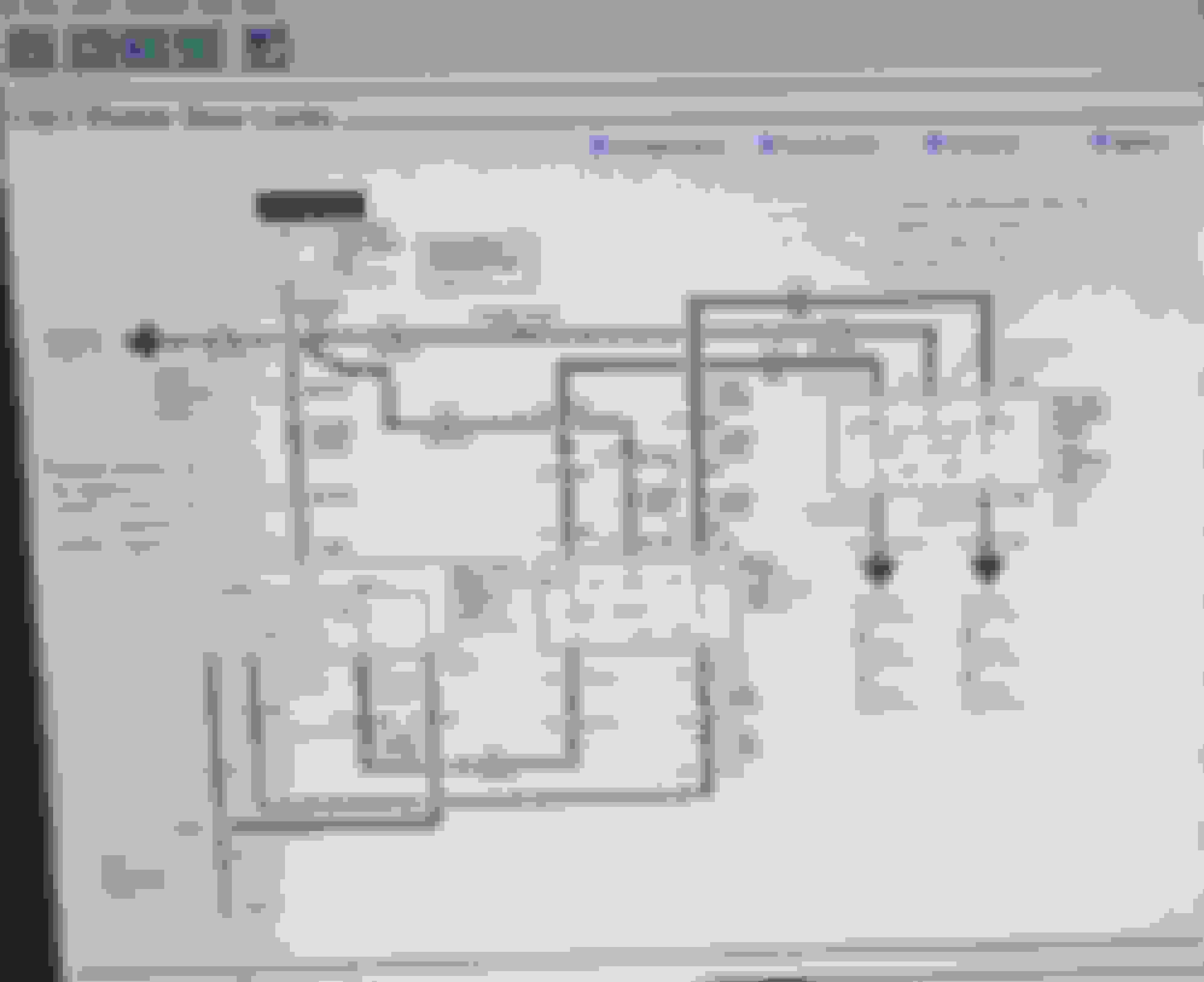
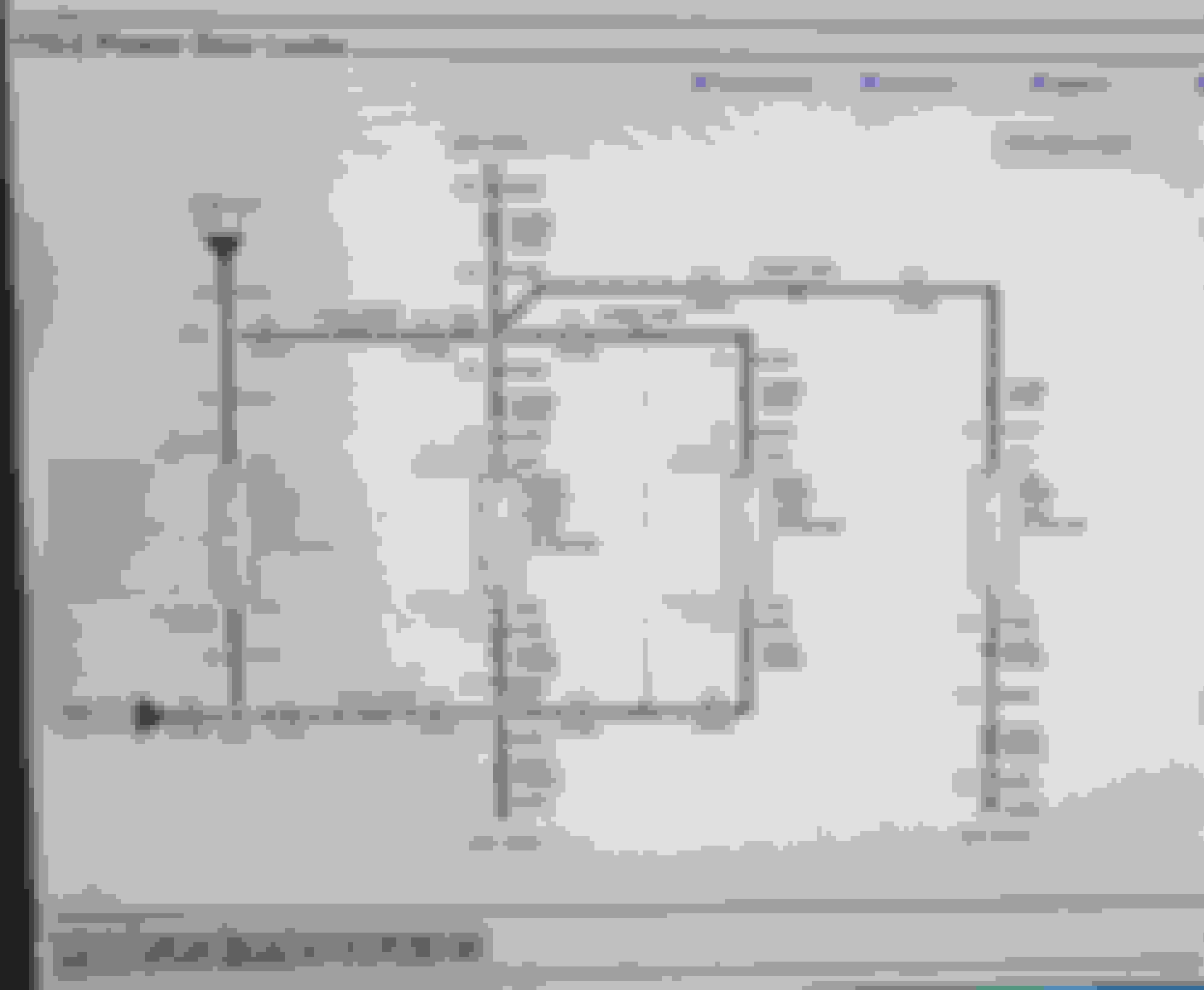
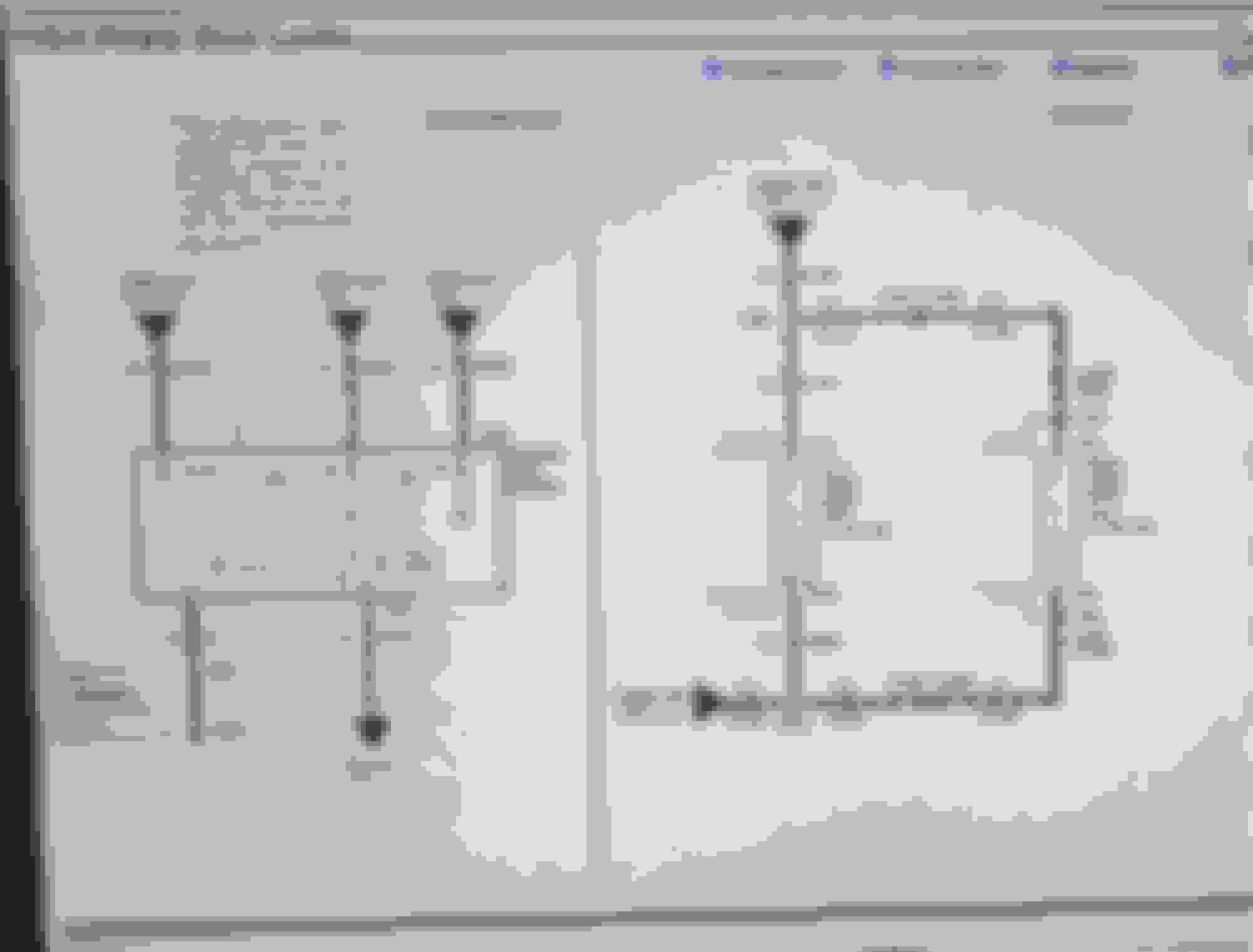
I got the factory service manual and I finally dug into the door lock and RKE wiring. This new location should be perfect for my aftermarket to plug into and give me a safe and protected area. I hooked it up last night and changed the operation of the Docooler RKE unit to function like "Diagram D" fig.4 positive and negative trigger (which I'm thinking is like reversible). If someone else has info to the contrary please let me know. Most of the Amazon reviews I read said that the manufacturer reversed the positive and negative trigger diagrams. They say they proved it in operation. Diagram B - Fig. 2 positive trigger has two inputs tied to ground or negative. Diagram C -fig 3 negative trigger has the three inputs tied to +12V which is positive. The only two outputs on the RKE are white = close signal and w/b which is open signal. I connected one white (close signal) to the C330 lock and w/b (open signal ) to the C330 unlock inputs into the van power lock circuit. The unit ties all the switch inputs to battery or ground and only has the two ouputs which I tied to the lock and unlock input lines on C330. I pressed my remote lock and and unlock and the door locks were backwards. I reversed the outputs on my RKE and now everything is working great! Those two lines are called "Door Lock Actuator , or Lock and Lock input signal" to the memory module. I will clean up the wiring and make it more permanent this weekend. I've also been researching the door lock system on my Ford and discovered it uses what is called a 5-wire reversible and it's supposed to be 0V at rest. Ford does not use any door lock relays on many vehicles for control but use extra wiring at the switches to eliminate them. I've included a picture of the RKE installation manual. I plan on posting some pics of the progress also.
Hi Teamtazman. I have a 1998 E350 V-8 extended van. I believe the actual Memory Lock Module comes with RKE and/or sliding side door. I have no RKE and a swinging side door. Yesterday I changed my plans for installing my aftermaket RKE unit in the passenger door like my old BullDog RKE was. Thanks JWA!!! I have found a place to install it behind the drivers side rear cabin accessory trim panel. I opened the panel and confirmed I have no factory RKE cables connectors or wiring harness. The service manual for the van shows only the factory RKE in this area and/or the Memory Lock Module. I did find a single unlabeled connector that was right by behind B pillar. It is a factory connector C330 to plug into a Memory Lock Module. In the absence of the Memory Lock Module they install a wire on the plug to route the lock signal to a wire running over the side door actuator. I have the swinging side doors with a power lock. Connector C330 has all the wiring for a door lock except the physical lock and unlock switches.
The cable going into the connector C330 has:
1. Battery
2. ground
3. lock signal
4. unlock signal
5. lock signal wire to the side swinging door lock actuator.
I got the factory service manual and I finally dug into the door lock and RKE wiring. This new location should be perfect for my aftermarket to plug into and give me a safe and protected area. I hooked it up last night and changed the operation of the Docooler RKE unit to function like "Diagram D" fig.4 positive and negative trigger (which I'm thinking is like reversible). If someone else has info to the contrary please let me know. Most of the Amazon reviews I read said that the manufacturer reversed the positive and negative trigger diagrams. They say they proved it in operation. Diagram B - Fig. 2 positive trigger has two inputs tied to ground or negative. Diagram C -fig 3 negative trigger has the three inputs tied to +12V which is positive. The only two outputs on the RKE are white = close signal and w/b which is open signal. I connected one white (close signal) to the C330 lock and w/b (open signal ) to the C330 unlock inputs into the van power lock circuit. The unit ties all the switch inputs to battery or ground and only has the two ouputs which I tied to the lock and unlock input lines on C330. I pressed my remote lock and and unlock and the door locks were backwards. I reversed the outputs on my RKE and now everything is working great! Those two lines are called "Door Lock Actuator. I have attached the pdf of the RKE manual and will post some pics of the connector location.
Last edited by cacarrillo; 06-11-2021 at 03:09 PM.
Reason: corrections
cacarrillo, thanks for the detail! I�m wrestling with aftermarket RKE on a �07 E350 wagon without factory RKE. Before reading your post, I poked around the B-pillar through the speaker opening. I saw a complex junction but no modules or loose connectors. How big is the C330 connector? How many wires/pins does it have?
Does anyone have to share a wiring diagram downstream of the door lock switches? I identified the output of the master lock switch in the driver door. There has to be a junction that splits the signal and changes wire colors. I�m curious how and where that happens. Could be irrelevant to the objective but I�m having trouble wrapping my head around how this relay-less system is wired.
I found a loose brown connector with 4 wires, no jumper. Wires are white with red stripe, red with white stripe, orange and black. All heavier gauge than anything at the door lock switches and lock actuators. I�m guessing this isn�t the RKE connector.
Hi, here are some photos of the area behind the drivers seat inside trim side panel and the cable and connector C330for the Memory Lock Module if it was installed.
Picture of open area inside panel. Normally this is where the RKE and Memory Control module would be mounted on side wall. Picture of connector C330 without factory option plug engaging side door actuator. Picture of connector C330 with factory option plug and connector on.
Last edited by cacarrillo; 06-12-2021 at 05:53 PM.
Reason: corrections and add photos
I remember seeing something about that for maybe the the power upgrade like DC sockets in the side for passengers? Or possibly for the side speaker. I'm looking now. I do not have that on my1998.
 05-16-2020, 10:09 PM