Hardware
#1
 09-20-2019, 11:21 PM

#2
09-21-2019, 12:34 PM

#3
09-21-2019, 02:01 PM
I was thinking of things that bolt to the block so more of a depth diameter and thread pitch of those holes. But a complete list based on year and application would really be something. Kind of like the parts catalogs are setup I guess.
#4
09-21-2019, 03:27 PM

49lexploded.jpg | Hits: 17819 | Posted on: 4/4/10 | View Low-Res
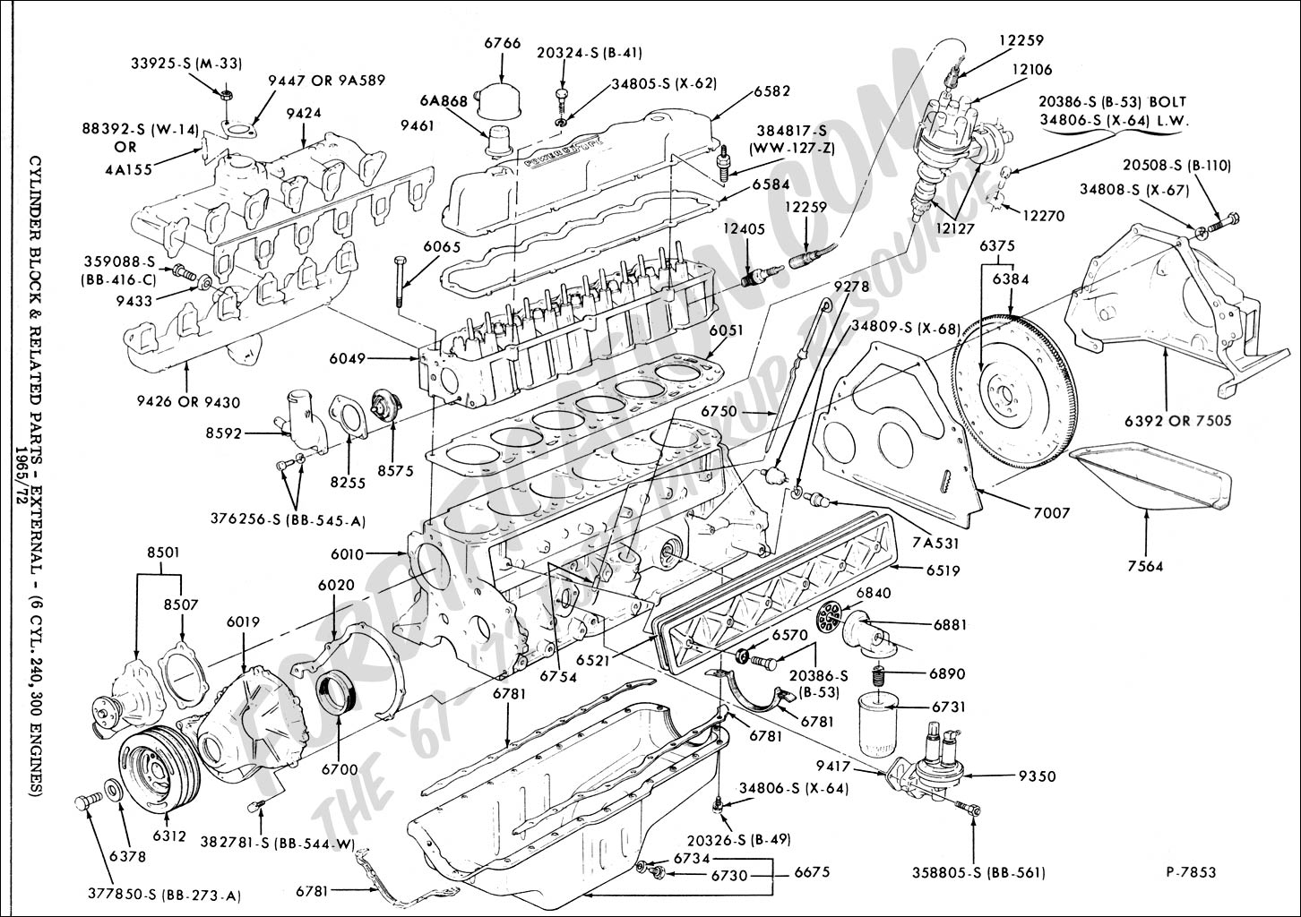
4.9L (300ci) I6 Exploded
IF THE IMAGE IS TOO SMALL, click it.
UPPER sizes:
8's bolts are 8mm (5/16")
9's nuts are 27mm
11's bolts are 9/16"
14 & 23 are 11mm (7/16")
24 & 25's nuts are 11mm (7/16")
46 & 49's bolts are 11mm (7/16")
50 & 52's bolts are 1/2"
74 is 1/2"
Smallblock distributors use Hold-Down Clamp
42 Oil Filter 16 Oil Filler Cap 17 PCV Breather Elbow 63 & 73
LOWER sizes:
29 is 13mm after '87; 1/2" before
14 for auto trans stamped F4TE-6A372-AA
See also:
 .
. 
Oil internal engine threads with engine oil, unless the threads require oil or water-resistant sealer.
Engine Block Casting Number Decoder
. . . . . . TORQUE SPECIFICATIONS
. . Item . . . . . . . . . . . . . . . . . . . . . . . . . . . N-m . . . . . . . . . . . . . Ft-Lbs
Connecting Rod Nut 55-61 40-45
Cylinder Front Cover 17-24 12-18
Cylinder Head Bolts (Follow bolt tightening sequence during each step) Progressively increase tightness using this sequence:
1st step: tighten all bolts to 67-75 N-m (50-55 ft-lb)
2nd step: tighten all bolts to 82-88 N-m (60-65 ft-lb)
3rd step: tighten all bolts to 94-115 N-m (70-85 ft-lb)
Damper to Crankshaft 177-203 130-150
EGR Valve to Intake Manifold 18-26 13-19
Flywheel to Crankshaft 102-115 75-85
Main Bearing Cap Bolts 82-94 60-70
Manifold to Cylinder Head Intake & Exhaust (Follow bolt tightening sequence) 30-43 22-32
Exhaust Manifold-to-Muffler Inlet Pipe 34-49 25-36
Oil Filter Insert to Cylinder Block 20-48 15-35
Oil Filter to Cylinder Block 1/2 turn after oiled gasket contacts sealing surface
Oil Inlet Tube to Pump 14-20 10-15
Oil Pan Drain Plug 21-33 15-25
Oil Pan to Cylinder Block (Follow bolt tightening sequence) 20-24 15-18
Oil Pump to Cylinder Block 14-20 10-15
Oil Inlet Tube to Main Bearing Cap 30-43 22-32
Pulley to Damper Bolt 48-67 35-50
Rocker Arm Bolt 24-31 17-23
Spark Plug to Cylinder Head 14-20 10-15
Valve Rocker Arm Cover (Follow bolt tightening sequence) 8-14 70-120 (In-Lbs)
Valve Push Rod Cover to Cylinder Block 2-3 18-27 (In-Lbs)
Water Outlet Housing 17-24 12-18
Water Pump to Block/Front Cover 17-24 12-18
Thermactor Pump Pulley to Pump Hub 12-15 110-130 (In-Lbs)
Throttle Body Attaching Nuts 19-27 14-20
Camshaft Thrust Plate to Cylinder Block 16-24 12-18
Distributor Clampdown 24-33 17-25
Intake Manifold Vacuum Fittings 8-13 6-10
Timing Pointer to Front Cover 17-24 12-18
Thermactor Air Manifold to Cylinder Head (Nut and Ferrule Assy.) 19-22 14-16
Thermactor Air Check Valve to Thermactor Air Manifold 22-26 16-19
Pressure Plate and Cover Assy. to Flywheel 27-39 20-29
Alternator/Thermactor Pump Bracket to Engine (all except bottom bolt) 40-55 30-40
Alternator/Thermactor Pump Bracket to Engine (bottom bolt) 53-71 39-53
Alternator Pivot Bolt 53-72 39-53
Thermactor Pump Pivot Bolt 40-55 30-41
Alternator Adjusting Bolt 40-55 30-41
Thermactor Pump Attaching Bolt 40-55 30-40
Air Conditioning Compressor to Mounting Bracket Bolts 24-31 18-23
Power Steering Pump to Mounting Bracket Bolts 40-55 30-40
Power Steering Pump/Air Conditioning Compressor Bracket to Cylinder Head Bolts 40-55 30-40
Power Steering Pump/Air Conditioning Compressor Bracket to Block Bolts and Nuts 55-70 40-50
Fan Blade to Fan Clutch Bolts 16-24 12-18
Fan Clutch to Water Pump 41-135 30-100
Oil Pressure Sender (Left Side Rear of Cylinder Block) 11-24 8-18
Engine Coolant Temperature Sender (Right Side Rear of Cylinder Block)
The following users liked this post:
#6
09-21-2019, 04:04 PM
#7
09-21-2019, 11:59 PM
Here is the 240/300/4.9 engine information.
Cylinder heads:
240 heads have a 68cc combustion chamber.
300 heads up to 1986 have a 76cc combustion chamber.
1987 and later heads have a 68cc heart shaped combustion chamber. These are the EFI heads
Heads up to 1984 have stud mount rocker arms with slot shaped pushrod holes in the head to act as pushrod guides.
Up to 1977 (unconfirmed) the 3/8" rocker studs used a 3/8 x 24 self locking adjusting nut.
The 1978 to 1984 heads use a shouldered 3/8 positive stop rocker stud with a 5/16" x 24 nut with no adjustment. The nut is torqued to the stud shoulder.
1985 and 1986 carburetor heads and 1987 and later EFI heads have pedestal mount rocker arms with round holes in the head for the pushrods.
1984 and earlier heads use a 4.810” long valve while the 1985 and later carb and EFI heads use a shorter 4.750” valve.
All have 11/32” valve stem diameter, 1.780" intake diameter and 1.559" exhaust diameter
SI valves is the main source for 240/300 valves that are the 4.750" and the 4.810" long stock lengths.
If the head is converted to screw-in rocker studs then the SBC 4.910” long valve can be used for oversize valve installation as well as the SI 4.810" long Ford 300 1.94"/1.60" valves.
The 1985 and later heads will need pushrod guide plates when converting from pedestal to stud mount rocker arms.
Chevy 250 six, Big Block Chevy, Ford 460 and Ford Cleveland 1.650" length rocker arms can be used with the screw-in studs.
Scorpion 1059 are 1.73 ratio pedestal mount roller rockers for the Ford 300 six. They are a direct bolt-on for the 1985 and later heads
Piston and connecting rods:
The 240 rod length is specified at 6.7947” and the 300 rod is 6.2097”. They are generally rounded up to 6.8" and 6.21"
The 1965-1968 240 and 300 rods have a .912” wrist pin diameter. 1969 and later rods have a .975” pin and an oil spit hole in the big end of the rod.
All rods are .992” wide at the big and small end.
Rod journals are 2.123”
240/300 block deck height is 10.00”
240 stroke is 3.18” and 300 stroke is 3.98”
Standard bore is 4.00" for all blocks.
Rotating assemblies will interchange between the 240 and 300 blocks.
A favorite combination is to use the longer 240 rod on the 300 crank.
This allows for a shorter and much lighter piston along with a higher rod length to stroke ratio.
The .912” pin rods allows the use of Ford 302 and 351W V8 pistons.
The .975” pin rods for 352 and 390 Ford FE V8 pistons.
The small 2.100” journal BBC rods have a .992” wide big end can be used with custom pistons.
These rods use the SBC 2.100" bearings.
The 300 crank rod journals are turned down form 2.123" to 2.100" to accommodates the BBC small journal rods.
The 6.385” long small journal BBC rod is available as an “off the shelf” item.
The 240/300 lifter is .875" and is common throughout the Ford six and V8 engine families.
The cam bearing housing bore on the Ford 300 engines manufactured after June 4th, 1985 was changed to make production installation quicker.
Previously all four housing bores measured 2.1440.
The late style block with the casting number E1TE-6015AA, has the following cam bearing housing bore dimensions:
Location Part # Bore Diameter
1 E5TZ-6261A 2.1590
2 E5TZ-6262A 2.1440
3 E5TZ-6262A 2.1440
4 E5TZ-6261A 2.1590
There are two main thrust bearings. A 3.567" OD flange and 3.602" OD bearing flange.
Trending Topics
#9
09-22-2019, 10:04 AM
What cylinder head does the engine have?
Is there any other information you would like?
#10
09-22-2019, 10:11 AM
It'll probably take me a couple of days to get through everything you posted. You have over delivered lol if there's anything not covered I'll just ask about those things later, and thank you for all of the information.
#11
09-22-2019, 01:48 PM
I looked back through your posts and it appears that the head has the 5/16" threaded rocker studs and the slotted pushrod guides which dates the head between 1978 and 1984.
If the block used the 1996 EFI pistons the compression ratio will be around 8.3
Can you look at the top of the piston through the spark plug hole to see what shape the piston dish is?
If the block used the 1996 EFI pistons the compression ratio will be around 8.3
Can you look at the top of the piston through the spark plug hole to see what shape the piston dish is?
#12
09-22-2019, 02:06 PM
I looked back through your posts and it appears that the head has the 5/16" threaded rocker studs and the slotted pushrod guides which dates the head between 1978 and 1984.
If the block used the 1996 EFI pistons the compression ratio will be around 8.3
Can you look at the top of the piston through the spark plug hole to see what shape the piston dish is?
If the block used the 1996 EFI pistons the compression ratio will be around 8.3
Can you look at the top of the piston through the spark plug hole to see what shape the piston dish is?
#13
10-02-2019, 01:11 AM