1993 E350 Motorhome Rattling and Power Loss
#16
 06-30-2019, 10:34 PM


I currently have the instrument cluster out and apart, trying to figure out how to fix the PCB. It appears to be two thin plastic sheets, laminated together in some way, each with copper tracings.
The problem is, on the driver's side of the panel, the sheet is delaminated, and appears to have dirt and crud in there. You can see how that side is discolored. Note, this is the right side when looking at the backside of the cluster.
Everything on the dash works, but I get a constant, dim CEL when the engine is running. Occasionally, I get a bright CEL, which I assume means it's throwing a code (which will hopefully help me resolve the problem with the way the engine is running).
I tried gently cleaning the sheet with electrical contact cleaner, it doesn't seem to have touched the mess on the plastic. I don't want to get too aggressive with it.
Looking around on eBay, all the used ones I've found are discolored the same way on the same side...
I've been searching like mad, can't find any info on how to fix this PCB. Any ideas?
Mike


#17
07-01-2019, 04:17 AM

I currently have the instrument cluster out and apart, trying to figure out how to fix the PCB. It appears to be two thin plastic sheets, laminated together in some way, each with copper tracings.
Everything on the dash works, but I get a constant, dim CEL when the engine is running. Occasionally, I get a bright CEL, which I assume means it's throwing a code (which will hopefully help me resolve the problem with the way the engine is running).
I've been searching like mad, can't find any info on how to fix this PCB. Any ideas?
If other clusters are showing the same effect and your CEL problem isn't frequently an issue on any Ford vehicle forums you have a PCM or other wiring issue. When the CEL does illuminate fully do you read the codes it might be signaling?
#18
07-01-2019, 07:55 AM

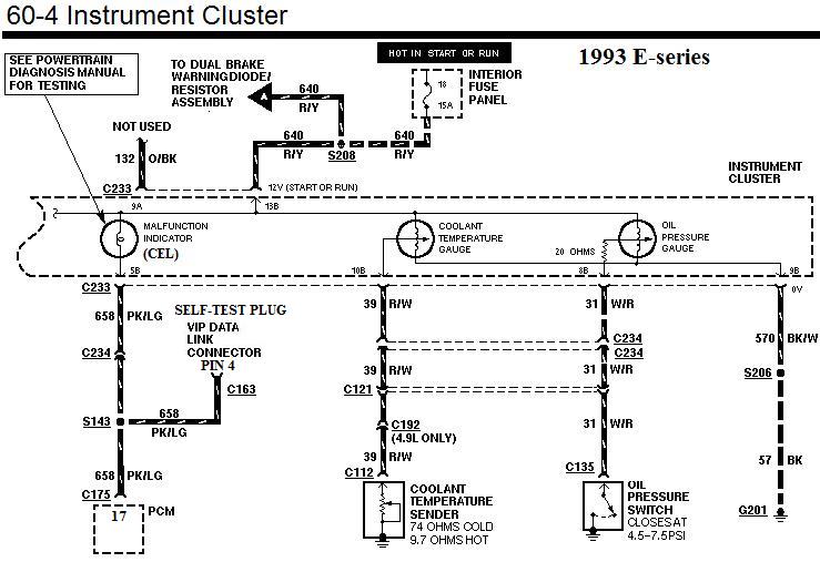
Pin #4 in the self-test plug (connector) turns on the CEL (MIL) when pin #4 goes to ground.
So looking at the below diagram the transistor Q10 is either leaking or the wiring between the pin #4 and the cluster is leaking to ground.
Attachment 281523
The rest of the circuit is below:
/
So looking at the below diagram the transistor Q10 is either leaking or the wiring between the pin #4 and the cluster is leaking to ground.
Attachment 281523
The rest of the circuit is below:
/
#21
07-01-2019, 03:39 PM
#22
07-01-2019, 07:42 PM
#23
07-01-2019, 08:50 PM
This is what the Ford manual say to do.
INDICATOR LAMP (MIL) ALWAYS ON: CHECK STO/MIL CIRCUIT FOR SHORTS TO GROUND
l If any Key On Engine Off Diagnostic Trouble Codes or Continuous Memory Diagnostic Trouble Codes are present, service before proceeding. If pass codes are present, continue with this Test Step.
l Key off.
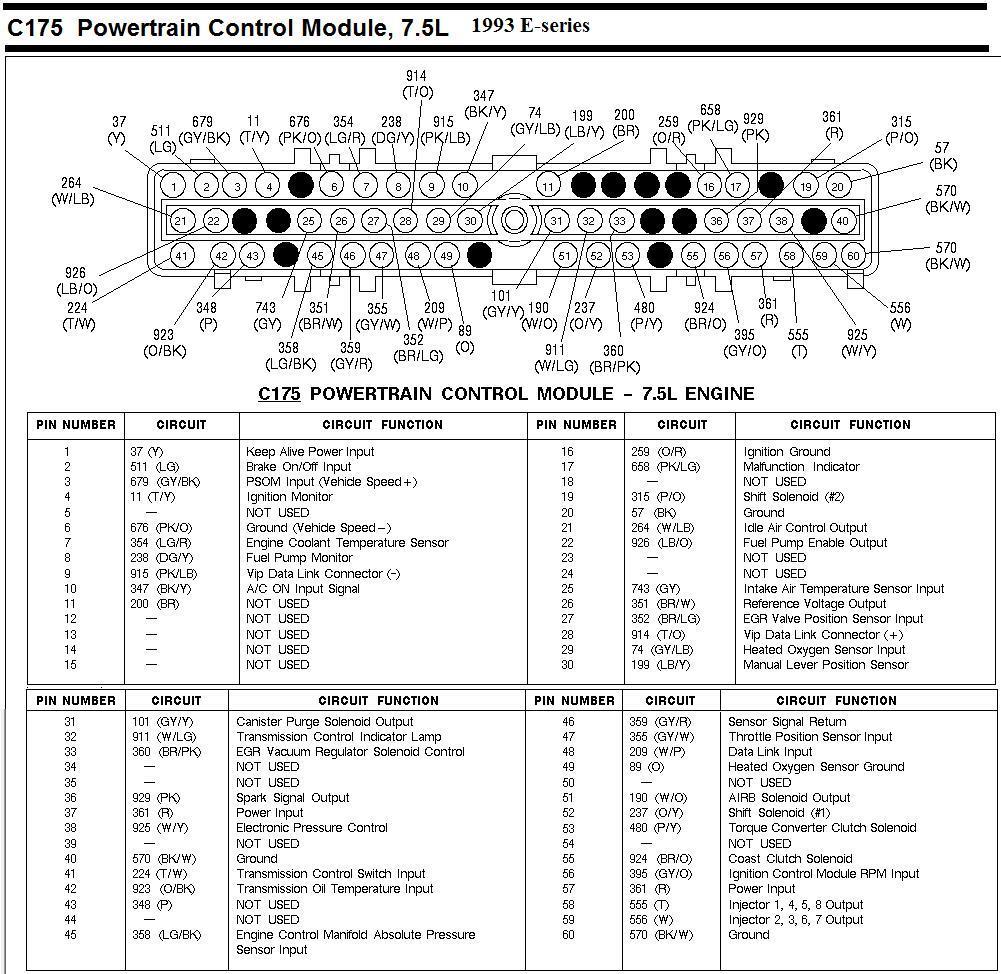
l Disconnect Powertrain Control Module (PCM). Inspect for damaged or pushed out pins, corrosion, loose wires, etc. Service as necessary.
l Install Breakout Box, leave PCM disconnected.
l Measure resistance between Test Pin 17 and Test Pin 40 at the Breakout Box.
l Is resistance less than 5.0 ohms?
Yes
SERVICE short circuit between Test Pin 17 and Malfunction Indicator Lamp (MIL), or between Test Pin 17 and the Data Link Connector.
REMOVE Breakout Box.
RECONNECT PCM.
RERUN �Quick Test�.
No
REPLACE PCM.
REMOVE Breakout Box.
RERUN �Quick Test�.
Now test pins 17 and 40 are the same as the PCM plugs pin #17 & #40.
Also pin #17 is the same as pin #4 in the self-test connector (plug) & pin #40 (Ground) is the same as pin #2 in the self test connector plug.
Of course first just unplug the PCM and see if the lamp (CEL) goes off.
STO/MIL is the same as CEL.
/
INDICATOR LAMP (MIL) ALWAYS ON: CHECK STO/MIL CIRCUIT FOR SHORTS TO GROUND
l If any Key On Engine Off Diagnostic Trouble Codes or Continuous Memory Diagnostic Trouble Codes are present, service before proceeding. If pass codes are present, continue with this Test Step.
l Key off.
l Disconnect Powertrain Control Module (PCM). Inspect for damaged or pushed out pins, corrosion, loose wires, etc. Service as necessary.
l Install Breakout Box, leave PCM disconnected.
l Measure resistance between Test Pin 17 and Test Pin 40 at the Breakout Box.
l Is resistance less than 5.0 ohms?
Yes
SERVICE short circuit between Test Pin 17 and Malfunction Indicator Lamp (MIL), or between Test Pin 17 and the Data Link Connector.
REMOVE Breakout Box.
RECONNECT PCM.
RERUN �Quick Test�.
No
REPLACE PCM.
REMOVE Breakout Box.
RERUN �Quick Test�.
Now test pins 17 and 40 are the same as the PCM plugs pin #17 & #40.
Also pin #17 is the same as pin #4 in the self-test connector (plug) & pin #40 (Ground) is the same as pin #2 in the self test connector plug.
Of course first just unplug the PCM and see if the lamp (CEL) goes off.
STO/MIL is the same as CEL.
/
#25
07-02-2019, 06:02 AM
A Breakout box (BOB) is a device that you can plug in between your PCM and the PCM plug. It has 60 jacks that you plug test devices into to check what each wire is doing that goes to the PCM.
To do the test above just unplug the PCM and do the tests between pin #4 of the self-test connector plug and a good ground point. The brake lines at the master cylinder is a good ground point or the NEG post of the battery.
Note that pin #2 will not be a ground while the PCM is unplugged.
Of course first just unplug the PCM and see if the lamp (CEL) goes out with the key in the run position.
Breakout Box: A service tool that "tees" between the PCM and the 60-pin harness connector. The breakout box contains 60 test pins that can be probed for EEC system testing.
Attachment 282975
/
#28
07-13-2019, 06:50 AM
#29
07-13-2019, 06:54 PM
How about replacing the entire dash w this super cool Dakota Digital dash?? My 1990 E150 is outside of their range which goes up to 1989. I'm pretty familiar whth these and I think 1989 and 1990 are the same as far as dash goes.
#30
07-13-2019, 06:57 PM