Need help with aftermarket warning lights
#32
The check engine light needs switched +12V. The computer completes the circuit to ground to turn on the light. There is likely a pull-up resistor internal to the computer that is backfeeding +12V to your light when the circuit is not active, causing the light to be on when it is intended to be off, and off when it is intended to be on.
#33
Join Date: Jan 2012
Location: Somewhere in the universe
Posts: 472
Likes: 0
Received 2 Likes
on
2 Posts
The check engine light needs switched +12V. The computer completes the circuit to ground to turn on the light. There is likely a pull-up resistor internal to the computer that is backfeeding +12V to your light when the circuit is not active, causing the light to be on when it is intended to be off, and off when it is intended to be on.
That make sence because it seems like it's doing the exact opposite of what it should be doing.
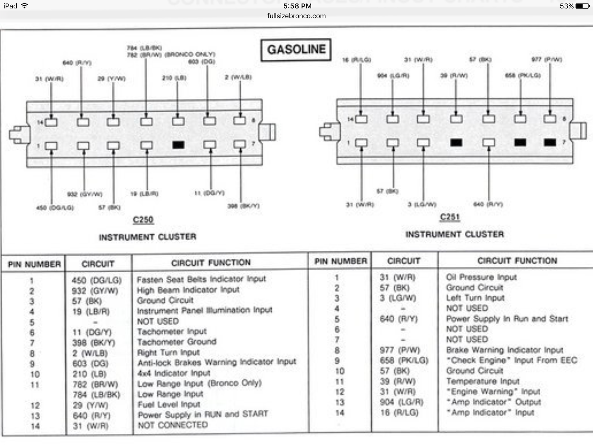
So basically I need to have the engine light hooked to not only a switched 12V, but the #9 658 (PK/LG) Check Engine Input From EEC as well?
#35
Join Date: Jan 2012
Location: Somewhere in the universe
Posts: 472
Likes: 0
Received 2 Likes
on
2 Posts
Also, what resistor would you have purchased? You think the one I ordered will be ok? I've been second guessing it.
After I ordered the resistor over the weekend I never got a confirmation nor did they take the money out of my account so I think I may get another crack at ordering it.
I did get my new COB dome light in though. I'll have to get out in the garage to Install it.
I also have to get under the truck to explore a little bit. I've got a pretty good size oil puddle on the garage floor right around the rear of the engine and front of trans. Oh boy.
I also have to do a tailshaft seal because it's leaking trans fluid a little bit from where the drive shaft goes in. This past summer must have been tough on it.
#36
Join Date: Jan 2012
Location: Somewhere in the universe
Posts: 472
Likes: 0
Received 2 Likes
on
2 Posts
Ok, got some stuff done on the truck this morning.
Added switched twelve volt to check engine light. No change.
Added resistor to charge light. No change, alt still holding at 11v.
Both lights still on.
Attempted to pull codes and for some reason I cannot pull them. There's no clicking from the engine compartment at all even after making sure the handheld was connected properly. The readout on the hand held is acting like there's no communication between it and the computer.
Tried both key on engine off and key on engine running. What the heck is going on here. I'm starting to regret I did this and I'm at a complete loss.
Please help.
#37
Join Date: Jan 2012
Location: Somewhere in the universe
Posts: 472
Likes: 0
Received 2 Likes
on
2 Posts
Just a rundown of what's what.
LT Turn Signal - Green/White Double wire ( Works Properly )
RT Turn Signal - White/LT Blue Double Wire ( Works Properly )
Brake Light - Purple/White ( Works Properly )
High Beam - Grey/White ( Works Properly )
Volt Gauge - Switched 12V ( Reading Properly )
Fuel Gauge - Yellow/White ( Reading Properly )
Oil Gauge - Supplied Independent Harness ( Reading Properly )
Water Gauge - Supplied Independent Harness ( Reading Properly )
PROBLEM:
Check Engine Light - Pink/LT Green wire and Switched 12V ( Staying on with and without switched 12V )
Low Charge / Battery Light - Red/LT Green wire and Switched 12V ( Staying on with and without Added Resistor ) Alternator not charging.
#38
Join Date: Jan 2012
Location: Somewhere in the universe
Posts: 472
Likes: 0
Received 2 Likes
on
2 Posts
I'm wondering if it makes a difference where the splices for the switched 12V and the Resistor is positioned that's making the issue for the charge light.
The resistor is positioned in line just off the Light. The Switched 12V is tied in further down the line so the resistor would only be making the difference for the light and not the rest. Wouldn't I have to tie the resistor in closer to the alt than the switched 12V tie in would be?
The resistor is positioned in line just off the Light. The Switched 12V is tied in further down the line so the resistor would only be making the difference for the light and not the rest. Wouldn't I have to tie the resistor in closer to the alt than the switched 12V tie in would be?
#40
Join Date: Jan 2012
Location: Somewhere in the universe
Posts: 472
Likes: 0
Received 2 Likes
on
2 Posts
Alright guys, the Alternator is charging.
Engine off at the battery is 12.77
Engine running is 14.08
Running with all accessories on is 13.04
Turns out I had the 12v and Low charge/ Low Battery wires going to the R/LG wire instead of the LG/R wire. Just had to stare at it for an hour to notice.
The light is still on though even with the resistor installed.
Now under light throttle while in park the Alternator is making a snapping noise??? It goes away at idle but everything above light throttle creates an electrical ark snapping noise that fluctuates with RPM.
Also figured out that my code reader is broke. The connectors pushed down inside the handheld when I plugged it in.
I'm almost at the point of just unhooking the Charge and Engine light and just check for codes at every oil change but I feal like that it would be half-assed and would never be able to get it out of my head?
#42
I don't know about the snapping noise, but as far as the circuits are concerned, it has to be complete for it to energize. If the circuit is broken anywhere between +12 and ground, current will not flow, whether that break is on the hot side or ground side of the load (light). Did anything change with the check engine light? Still off when the key is in run and on when the engine is running?
#43
Alright guys, the Alternator is charging.
Engine off at the battery is 12.77
Engine running is 14.08
Running with all accessories on is 13.04
Turns out I had the 12v and Low charge/ Low Battery wires going to the R/LG wire instead of the LG/R wire. Just had to stare at it for an hour to notice.
The light is still on though even with the resistor installed.
Yep been there done that with the R/LG x LG/R and other color wires sitched too. Makes things much more PITA to figure out.
As now for the charging LED always on, with good charging occurring. I suggest replacing the charge LED with the old lamp/resistor to see what will happen. This will be the best test to figure out if there is a problem.
LED's require very little current to light up over a lamp. So it may be lighting up with just the alternator energizer current where as the lamp will not glow until the "fault" circuit is activated.
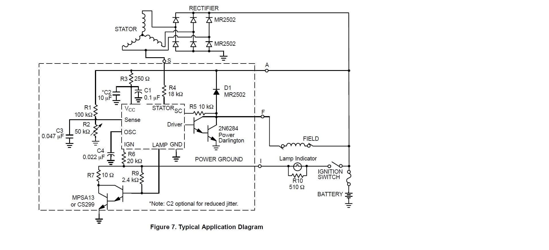
I have reversed engineered the voltage regular of these alternators and see this is what could be happening.
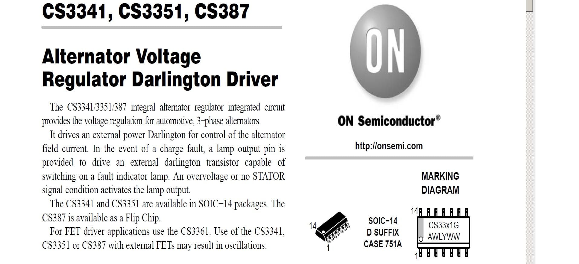
Here is the IC that is inside the regulators.

And here is a schematic that is with the datasheet of the above IC. Interesting note: Of the few regulators I took apart the schematic below was almost the same! A few resistors were different value, but not too far off from the application schematic.

Thread
Thread Starter
Forum
Replies
Last Post
78 & 87 Super Cab
1957 - 1960 F100 & Larger F-Series Trucks
37
08-12-2014 10:09 AM
snipa
1948 - 1956 F1, F100 & Larger F-Series Trucks
14
07-07-2005 09:07 AM


