When you click on links to various merchants on this site and make a purchase, this can result in this site earning a commission. Affiliate programs and affiliations include, but are not limited to, the eBay Partner Network.
Wanted to share my 2LO/Auto hub override mod. This has surely been done before (did it on my ’03), but I haven’t seen it here on this ‘17+ forum, so I thought I’d write it up. It took only 15 minutes to do and less than $10, and I think is now one of my favorite mods for truck with ESOF.
I now have an upfitter wired so that when I turn it on, the auto hubs are prevented from locking when switching into 4HI or 4LO, or if you are already in 4WD, the hubs unlock. If in 4WD, I can flip the upfitter switch to unlock the hubs, make a tight turn or maneuver, and then flip the switch again to re-lock the hubs. When maneuvering a trailer in a tight spot or carefully leveling it, I can flip the hub override switch, shift to 4LO (now 2 LO), and maneuver the trailer on pavement in low range without front axle binding (say, when putting it onto leveling blocks). This locking/unlock can be done without shifting the transfer case – no need to stop and shift to neutral each time you want to lock and unlock (in LO range). Just do it the first time, and control the hubs with this switch until you are ready to go back to HI range. It is very easy to install and completely reversible. It does not do anything to the transfer case - it only effects the front hubs.
Also, I’ll just beat some of you to it – those with manual hubs and manual transfer case, you can use 2LO just by selecting it manually and not locking the hubs. Yes, I know. You just keep your hands on your **** and keep working it back and forth. Let those of us with ESOF do our thing.
To do this mod, you’ll need a 5 pin 12V relay (available at any parts store/Amazon/etc) -- It needs to have 5 pins (to include pin 87A, which is the Normally Closed (NC) contact). Other parts include a couple feet of wire (14ga), some crimp terminals, electrical tape, and either upfitters or your own installed switch with 12V power. This writeup is done using the upfitters, but you can just as easily do it with a switch you wire beneath the dash to control the relay.
It requires cutting a single wire in the hub vacuum solenoid under the hood, and connecting the ends of that wire across the NC contacts in the relay. This way, with the new relay de-energized, the hub vacuum solenoid opens and closes like normal whenever you shift into and out of 4WD because the signal travels through the NC contact. Once you energize the new relay (via upfitter switch or other switch), the NC contacts open and power to the hub vacuum solenoid is interrupted, which will unlock the hubs. As soon as you de-energize the solenoid, the power to the hub vacuum solenoid is restored, the solenoid vacuum port opens, and the hubs lock again (assuming you are in 4HI or 4LO).
If you flip the hub override switch before shifting into 4WD, the truck senses it and will give a “check 4x4 system” warning message on the dash. It still shifts the transfer case. When the swtich is turned off, the hubs lock and you’re back in 4WD. If you first shift into 4WD and then flip the hub override, no warning message is displayed.
So, some pics of the install:
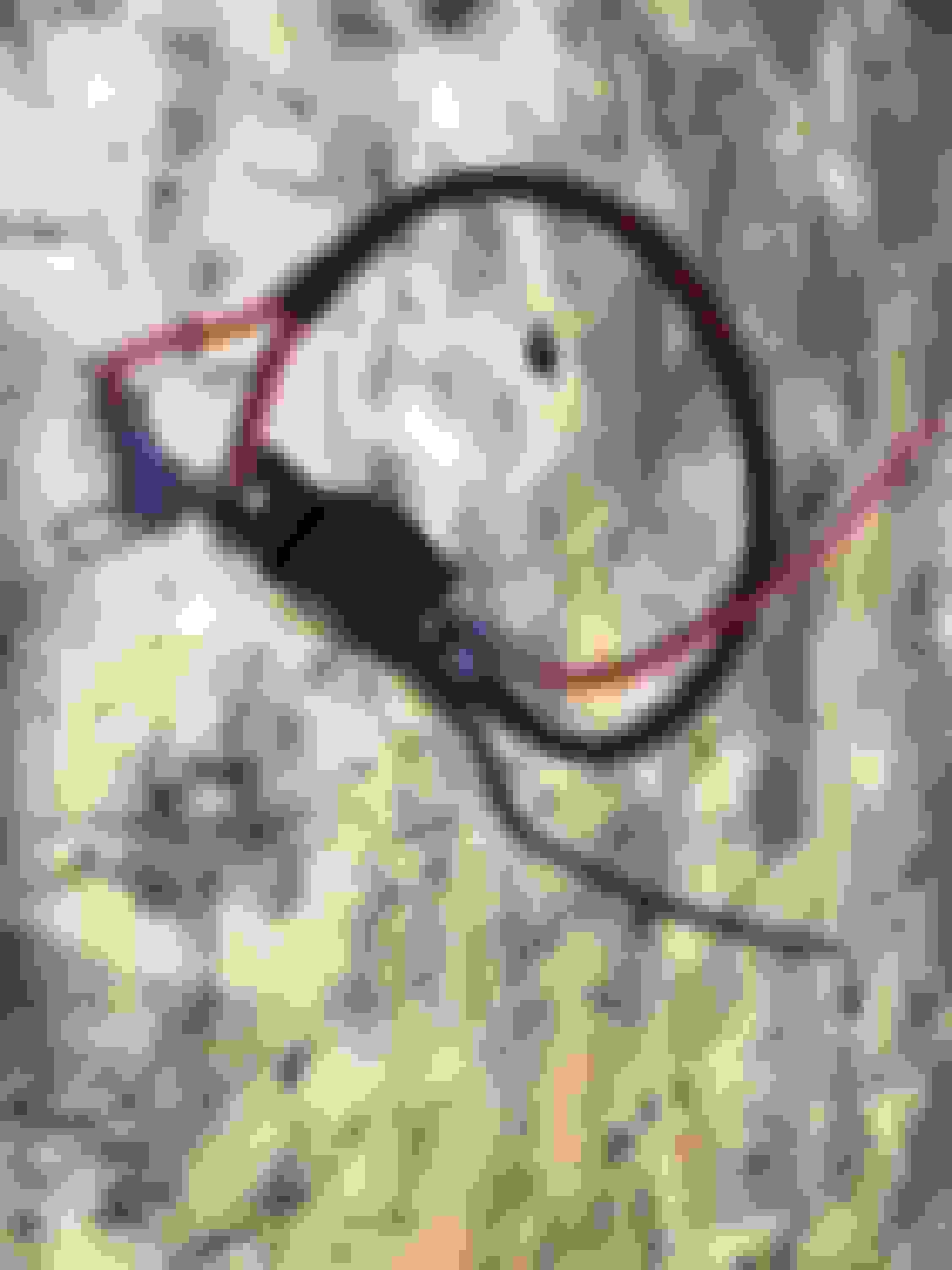
Vacuum hub solenoid location (on a 6.7, anyway). It's the 2-wire plug in the middle of the picture. Push the release clip down and pull the connector off.
Here's the relay I added. Block wire goes to ground. red wire on the right goes to upfitter/switched power, the two with terminals on them are spliced inline with the vacuum solenoid ground.
Cut the vacuum solenoid ground wire and run to the NC contacts. Connect to pin 30 and pin 87A. Doesn’t matter which side goes to which pin. Hook the upfitter switch power to pin 86, and wire pin 85 to ground.
Now, tape it all up as neat as you like:
Enjoy!
Last edited by Y2KW57; 04-12-2020 at 11:11 AM.
Reason: Added "2WD Low" to title for search engine purposes
I have installed this mod on my truck and I want to share a slight modification I made to eliminate any error messages by not activating the circuit in a proper sequence. The standard implementation is to use a SPST relay to interrupt the power to the vacuum solenoid and to power that relay from an upfitter switch. If you break the vacuum solenoid circuit when the truck is trying to activate it, you can get an error message or light on the dash. This is because the truck can "see" the resistance of the vacuum solenoid and it monitors the circuit. I don't want to worry about those error messages so I decided to modify the circuit to include the ability to keep the truck computer happy with the circuit whenever it is activated.
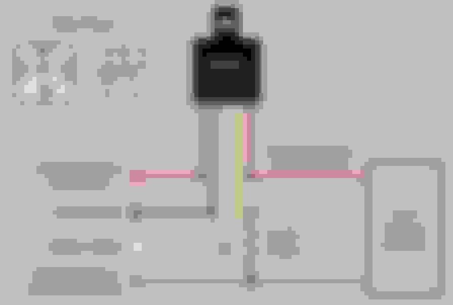
First the relay and harness. The standard Bosch automotive "cube" relay can also be had as a SPDT configuration. The red wire is the "extra" connection not included in the standard SPST configuration. Using this type of relay with the appropriate harness you can create the scenario in the schematic below.
Now for the revised schematic:
Explanation: The SPDT relay has a Normally Closed (NC) and a Normally Open (NO) circuit available. I broke the red wire on the vacuum solenoid cable and wired it to the NC circuit. Without any voltage to the relay coil the circuit is intact and the truck will activate the solenoid when asked to. The truck computer "sees" the resistance of the vacuum solenoid coil and all is well. This is the same exact wiring that people have been doing with the SPST relay mentioned earlier.
When you activate the upfitter switch and energize the SPDT relay coil, the circuit to the vacuum solenoid is broken and is instead routed through the 150Ω resistor. This removes power from the solenoid, disabling the 4x4 engagement, but keeps the computer happy because it "sees" the resistor and "thinks" it is the solenoid, preventing error messages. See below.
I measured the resistance of the vacuum solenoid and found it was 50Ω. With 14.4 volts applied to the circuit it will dissipate a little over 4 watts of heat. A 5 watt resistor is physically large and I wanted this to be small so I did a little testing and determined that the truck computer was satisfied with a 150Ω resistor in the circuit. This resulted in 1.3 watts of heat being dissipated - easily handled by a 2 watt resistor, which is physically much smaller than a 5 watt unit. Armed with this info, I cut the yellow wire close to the relay socket. I soldered the 150Ω resistor to the socket lead and then soldered the cut yellow wire to the other end of the resistor. I covered the entire joint with heat shrink and then wrapped the entire bundle with loom and Tesa tape.
Next, I disconnected the harness from the vacuum solenoid and stripped back the tape and loom. Using my Klein wire strippers I removed a 1/4" strip of insulation from the brown / blue wire. Then I soldered the yellow wire mentioned earlier to the brown / blue wire.
I cut the red wire and wired the relay into it. I also connected the other wires as depicted in the schematic. I used an open stud on the firewall for the relay coil ground and to physically mount it.
I can operate upfitter switch #1 to defeat the vacuum solenoid whenever I wish without setting a trouble code or light.
EDIT: I have received several PMs asking for clarification on the wiring. I created this drawing to help those who have issues with schematic drawings:
Last edited by B-ManFX4; 04-05-2024 at 11:40 AM.
Reason: Added wiring drawing.
Write up and pictures are excellent! Not the most accomplished individual with electronics. I would appreciate more information about the relay. I'm thinking the relay needs to be normally closed so that the ESOF will function as intended when the relay is not activated. Is the relay used a normally closed or normally open type? A part number or place of origin could also be helpful. The rest I'm confident I can deal with.
Write up and pictures are excellent! Not the most accomplished individual with electronics. I would appreciate more information about the relay. I'm thinking the relay needs to be normally closed so that the ESOF will function as intended when the relay is not activated. Is the relay used a normally closed or normally open type? A part number or place of origin could also be helpful. The rest I'm confident I can deal with.
You're correct.. Normally Closed is what you need. So you need either a pure NC relay, or as nuctrooper used, you get a 5 pin relay that has both the NC and NO contacts. And if you get http://a.co/0NpH0f0 those from Amazon, you have 4 relays for pretty few bucks. Then you have extras to do all the other mods you find here.
If Ford would just put a center diff in these trucks we could have full-time 4x4 with zero binding, high or low range. My primary purpose of this mod would be to quickly disengage the hubs while making a sharp turn on mixed traction surfaces (snow covered to plowed). Nuctrooper, how quickly do the hubs engage and disengage?
 07-01-2018, 10:30 PM